(C) 2024 G. Forrest Cook
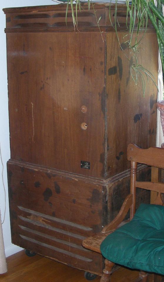
Leslie 31H Cabinet
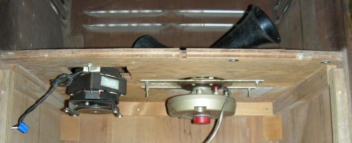
Leslie 31H Tweeter Horn Rotor
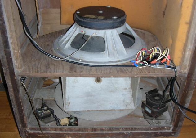
Leslie 31H Woofer Baffle Rotor with Solid-State Relays
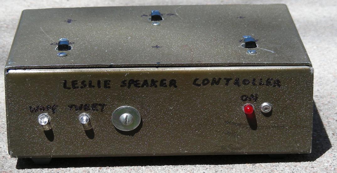
Automatic Leslie Controller Front
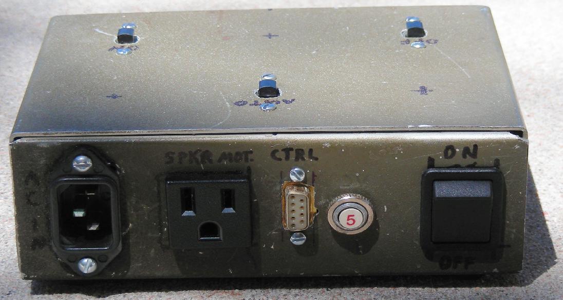
Automatic Leslie Controller Rear
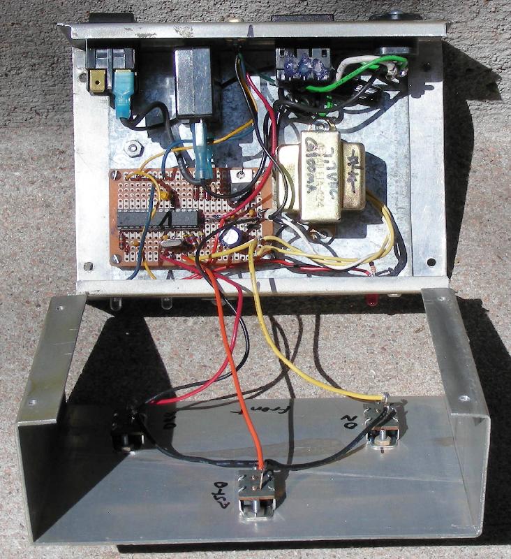
Automatic Leslie Controller Inside
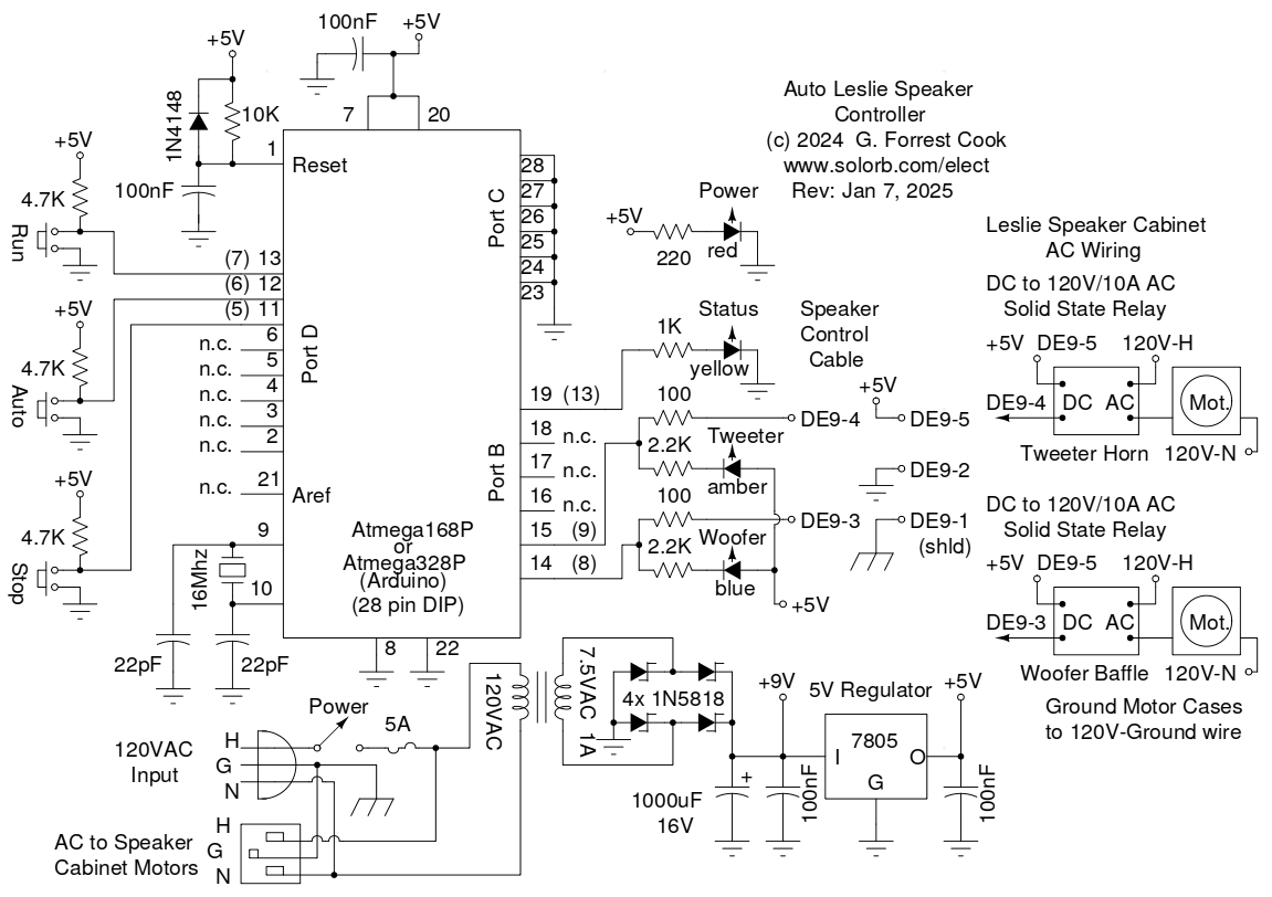
Automatic Leslie Controller Schematic
This project involves the construction of a solid-state dual motor controller for a 1940s vintage Leslie 31H High Boy organ speaker. This particular speaker has had a number of modifications from its original configuration. It came with no amplifier and the original woofer and tweeter had been replaced with newer components. The replacement Woofer is a 15" heavy-duty Cerwin-Vega type. A non-original cross-over circuit had been added to the two speakers. Both of the low-speed motors had worn out rubber friction disks which interfered with the operation of the high-speed motors. Those motors were removed and screwed them into the bottom of the cabinet for safe keeping.
The speaker had been stored in a barn in Iowa for many years, along with its companion Hammond B3 organ. It needed extensive cleaning to remove a lot of dust and grime. The cabinet would still benefit from sanding and refinishing the outside surface. There are many chips and scratches in the wood from being hauled around to various gigs over the years. The previous owner, a talented organist, said that the organ and speaker were used in the 1965 US tour of the British band Herman's Hermits, so it could be considered a part of Rock-n-Roll history.
A Leslie speaker makes a very unique and amazing sound. It combines volume-modulating tremolo with pitch-shifting Doppler-effect vibrato. The sound produced changes quite a lot depending on where the listener is in the room. Some Leslies only have a rotating woofer baffle, which does make a really nice sound. Leslie speakers that also have a rotating tweeter horn produce an even more interesting sound.
After some experimentation it was found that the most interesting sounds come from the speaker when the rotors are either spinning up or down. When in auto mode, this controller makes each motor spin its rotor up and down independently to make the most of that effect. The controller also allows the player to start and stop the motors manually for a more traditional effect.
This project involves potentially lethal high voltages such as 120 VAC. The project should only be taken on by someone who has experience working with high voltage circuitry. The power cord should always be unplugged when working on the circuitry.
A not-too-pretty used aluminum box was chosen for housing most of the controller circuitry. The box was drilled and filed to accomodate the various buttons, LEDs, sockets and connectors. A few remaining holes were fitted with hardware to seal up the box.
The Arduino-based controller was hand-wired on a Radio Shack prototype board. The board holds the Atmega 168P processor chip and DC power supply components. The various interface connections were wired between the board and the buttons, LEDs and speaker control cable connector. Small wire loops were fashioned on the top of the board using tinned copper wire, these allow the external wiring to be soldered to the edges of the board. The chip was programmed on an older Arduino Diecimila board and was transferred to the prototype board. The AC wiring was added between the power connectors, circuit breaker, power switch and power transformer.
The two solid-state relays which turn the motors on and off were mounted next to the woofer in the speaker cabinet and the AC and control cables were routed out of the speaker box to the controller box. Be sure to use strain relief on any external cables. A 1/4" phone jack was added to the back of the cabinet to connect the speaker cross-over board to the external amplifier. The Spartacus Max amp has been used to drive the speaker, it works with either a high-impedance electric guitar signal or a line-level signal from the B3 organ.
Labels for the various switches, LEDs and connectors were hand-drawn on the box. The military-green crinkle paint that came on the box does not adhere well to stick-on labels. It's an ugly prototype, but it sure sounds good.
AC power is input to the controller box and routed through a switch and fuse or circuit breaker. The switched AC power feeds the 7.5VAC power transformer and Leslie speaker cabinet power cable. The 7.5VAC transformer's output is rectified by a bridge of 1N5818 Schottky diodes and filtered by a 1000uF electrolytic capacitor to produce around 9V of unregulated DC power. The 9V DC power is run through a 7805 voltage regulator to produce 5V for powering the Arduino microprocessor. The red Power LED is powered by the +5V supply through a current limiting resistor.
The Arduino Atmega 168 processor has 16Mhz crystal clock circuit and a slow-on reset circuit. Three Port D processor inputs are connected to the Run, Auto and Stop buttons, which are active-low and have 4.7K pull-up resistors. Three of the Port B outputs are connected to yellow, amber and blue status LEDs via current limiting resistors. The (optional) yellow LED is mounted on the processor board and can be used for software debugging. The amber and blue LEDs are high-brightness types and are mounted on the front panel of the controller box to show woofer and tweeter motor activity. The two motor control signals are also routed to the speaker cabinet via 100 ohm current limit resistors and the remote cable.
Inside of the Leslie speaker cabinet, the AC power is routed through a pair of DC to AC solid state relays which control power to the two motors. The two low-active DC relay control signals and the common +5V bus are connected to the controller box via a shielded multi-wire cable. The wire's shield is connected to the controller case (AC ground).
The controller software can be programmed onto either an Atmega 168P processor via an Arudino Diecimila board or an Atmega 328P processor on an Arduino Uno board. Once the software has been uploaded to the processor, the chip can be removed from the Arduino board and installed into the controller's circuit board. Either of the Arduino boards can also be used inside of the controller if the appropriate interface circuitry is connected to the board. An Arduino Nano board could probably be used as well although this has not been tried.
See the Arduino Sketch source code for details on the software.
The controller starts up in Manual/Off mode. Pressing the Run button causes both motors to spin up, releasing the Stop button causes both motors to spin down.
Pressing the Auto button causes the controller to take over the motor control. Each motor has its own on/off timing sequence that is tuned in the software so that the motors spin up or down but never stop fully or stay at their top speed for any length of time. If the Run button is pressed while in Auto mode, both rotors temporarily spin up to full speed until the Run button is released. Pressing the Stop button causes the Auto mode to end and the rotors spin down.
An automatic time-out is included in the Auto mode, it prevents the motors from running constantly if the player walks away. This helps prevent excessive wear on the moving parts. The time-out is set to 5 minutes, the value can be easily changed in the software. Whenever the Run button is pressed while in Auto mode, the time-out counter will be reset to zero.
It would not be too difficult to expand the auto mode in this controller to support different motor control timing parameters. One or more mode switches could be wired to the unused Atmega Port D inputs to select different timing values for the auto mode section of the sketch.
Another variation to this project would be to add some kind of variable speed controller to the motor circuitry. An old-school AC light dimmer was tested on the motors and worked for running the motors at slower speeds. A light dimmer would probably interact with the solid state relays, mechanical relays and associated driver circuitry would probably be required.
Back to FC's Music Circuits page.