Low power FM Stereo Radio Station
This circuitry is used for generating a high quality FM stereo multiplex signal that is suitable for driving mono FM transmitters. The Rev E2 FM stereo multiplex generator is the most recent design in a series of circuits that have appeared on this site. This version features improvements to the audio mixer stage, better gain adjustments in the audio filter stage and a rework of the multiplexer stage. When it is adjusted properly, the Rev E2 design produces an FM stereo signal with excellent fidelity.
This is an advanced-level project, it should only be attempted by someone with a high level of electronics experience. A professional-grade oscilloscope and an audio signal generator are absolutely required for aligning this circuit. If you don't have a fair amount of experience tweaking and aligning electronics circuits, you might want to seek out help from someone who does.
Note that the Front End Mixer portion of this circuit is completely optional, it is mostly useful for portable self-contained transmitter setups. Stereo audio can be sent directly to the Rev E multiplex board. Either one or two VU/clipping meters can be built, two meters are generally recommended since they give an indication of the stereo balance.
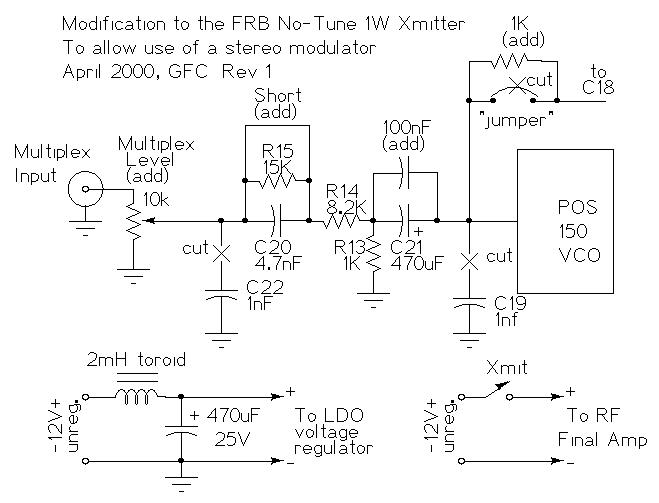
The Free Radio Berkeley 1W "No Tune" PLL synthesized unit (year 2000 version) was used as the transmitter for this project. If you use the FRB board, these modifications should be performed on the transmitter. The modifications involve the removal of the audio input filtering components and the addition of an input level control. The input filter mod allows the 19Khz and 38Khz signals to pass through to the transmitter's modulation stage. Wavemach Communications has a 2W mono FM transmitter that looks like it would work with this circuit, some audio front-end mods may also be required.
It is important to have a stereo compressor between the signal source and the transmitter. When properly set, a compressor can save the operator from having to "ride" the volume level between the point of good modulation and the point of distortion (clipping). The Alesis Nano Compressor and the FMR Audio Really Nice Compressor (RNC) are good choices. The Alesis 3630 compressor should also work.
Setting up the compressor is a bit of an art form. Listen to your over-the-air signal and adjust the compressor for the best sound while listening to some typical program material. For music, I usually set the attack/decay times fairly fast and the compression ratio level to a spot where the transmitter doesn't clip but the audio still has some dynamic range (punch). Note that the compressor output level and compression ratio level interact and should be adjusted together.
For the best signal coverage, an efficient and properly tuned antenna is a must. The Hula Hoop Ground Plane Vertical Antenna is a good choice for many installations. This J-Pole antenna also works quite well if it it is installed high up and away from nearby metal objects.
It is the operator's responsibility to run the transmitter in accordance with the frequency regulating authority of their country, it may be necessary to use an output attenuator on some transmitters.
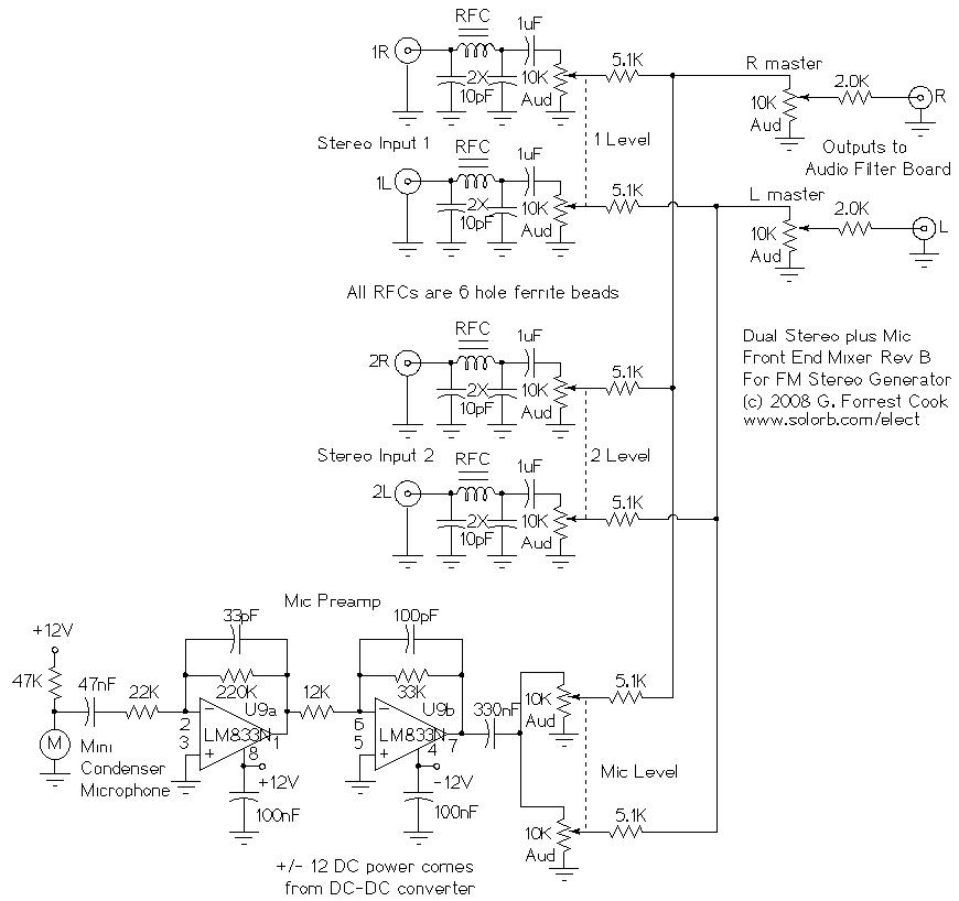
The (optional) mixer stage uses passive mixer circuits for mixing the two stereo inputs. The two stereo inputs are filtered with LC Pi filters to remove stray RF signals. The condenser microphone is biased with a 47K resistor then the signal is boosed with two stages of op-amps. The microphone signal is split into the left and right channels with a double 10K audio taper potentiometer. The outputs of the stereo input and mic volume controls are padded with 5.1K resistors, this prevents the control from one channel pair from changing the volume of another channel pair at the top settings. The left and right signals are fed through individual master volume controls. These can be used to set the maximum signal level and to balance the channels. The 2K pad resistors on the master volume controls prevent scratchy sounds that show up when turning the controls all the way up.
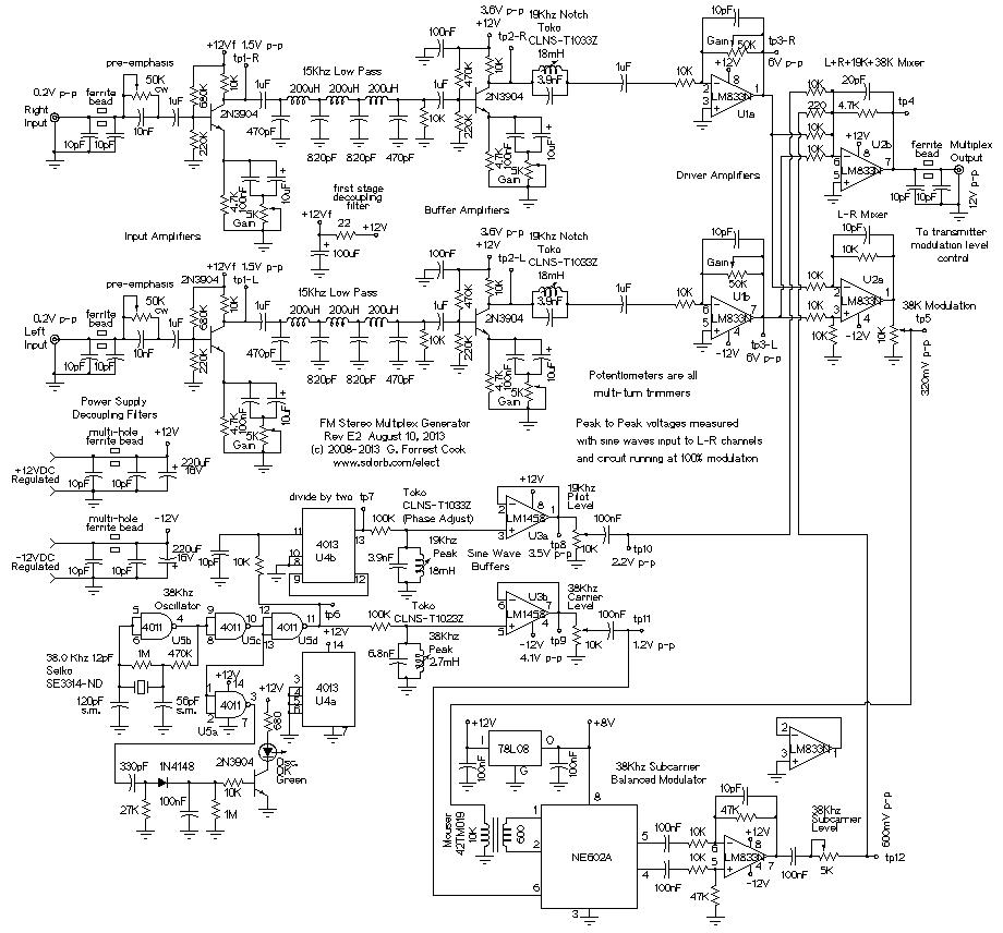
The two inputs of the multiplexer board go through a ferrite bead and two 10pF capacitors to remove any stray RF energy. The signals go through an adjustable pre-emphasis filter which reduces the bass. The audio signals then go to adjustable gain buffer amplifiers which drive three-pole LC lowpass filters. The output from the lowpass filters go to adjustable gain buffer amplifiers which drive 19Khz notch filters. The 19Khz filter removes audio energy that can cause unwanted hetrodyne frequencies, it also improves the roll-off of the low pass filter in the frequency range between 15Khz and 19Khz. The LM833N driver amplifiers increase the audio signal enough to drive to the following LM833N sum/difference amplifiers.
An FM stereo modulation waveform consists of a mono (Left + Right) baseband audio signal plus a (Left - Right) supressed-carrier modulated 38Khz subcarrier signal plus a 19Khz sine wave pilot tone.
The L-R mixer amplifier is a difference amplifier, it produces the signal that is used to modulate the 38Khz wave via the NE602A balanced modulator IC. The L+R+19K+38K mixer amplifier combines the Left and Right baseband audio signals with the 19Khz pilot tone and the 38Khz modulated subcarrier to produce the multiplex output signal.
The NE602A gilbert cell balanced modulator combines a 38Khz carrier signal and a balanced modulation signal to produce a balanced supressed-carrier dual-sideband modulated output. The audio transformer on the input converts the modulation signal into an isolated and balanced signal for the NE602A. The balanced output signal is sent to an LM833N op-amp wired as a differential amplifier with a gain of 5. The 78L08 regulator provides 8V for the NE602A IC.
The 38Khz oscillator produces a square wave signal, that is fed to the 4013 flip-flop IC which divides the frequency in half to produce 19Khz. The 38Khz and 19Khz square wave signals are fed to two L-C resonant circuits to produce sine wave signals. The two sine waves are amplified by the sine wave buffer ICs to produce 38Khz and 19Khz sine waves. The 19Khz sine wave is fed to the L+R+19K+38K mixer. The 38Khz sine wave is fed to the carrier input of the LM13700 modulator.
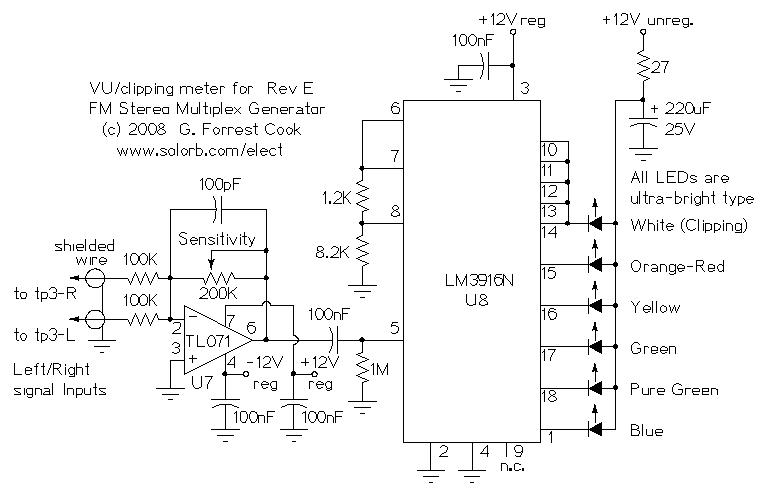
The VU/clipping meter combines the left and right audio signals from the driver amplifier outputs in the TL071 summing amplifier. The combined signal is amplfied by the TL071, then fed to the LM3916N VU meter IC. The colored LEDs are wired as a 5 stage VU meter, the upper 5 stages are connected together to the white Clipping indicator LED. The LM3916N is wired to be in the dot display mode, the parallel connections to the white LED cause the LED to light for all levels above clipping, making the clipping indication more visible. Power to the LEDs is taken from the unregulated 12V supply to keep the LED switching noise isolated from the audio circuitry.
The power supply is not shown on the schematic. A +12VDC source is required, this can be anything from a lead acid battery to a wall-wart to a standard analog power supply. Beware that most wall-warts have misleading voltage ratings. The power supply should be rated to produce at least 2 amps. This source is tied to the +12V unregulated inputs.
The +/- 12V regulated voltages are provided by a MeanWell model DKE15A-12 DC-DC converter, that is powered by the +12V unregulated supply. Jameco.com sells these devices. This allows the transmitter to be run from a single 12V source such as an automobile or a battery. Alternately, a +12V/-12V regulated line-powered power supply could be used to power the whole transmitter, just tie the +12V regulated and +12V unregulated lines together. Each op-amp should have a 100nF bypass capacitor between its V+ and V- supply input and ground. The 4011 and 4013 ICs should also have 100nF bypass capacitors across their VDD and ground pins.
See the Wikipedia article on FM modulation for reference information. This Angelfire article has a good explanation of FM stereo receiver demultiplexing theory.
Alignment of this circuit requires connecting two sine waves of differing audio frequencies into the audio inputs. This Stereo Test Tone Generator circuit works well for the job. Other sine wave sources can be a pair of audio test generators, one or two PCs running sine wave generator software, or a test tone CD.
Adjust both pre-emphasis potentiometers to the minimum resistance (full bass). The sine waves should be connected to the left and right inputs of the mixer board and the levels should be adjusted to 0.2V on the audio input of the multiplexer board. An oscilloscope should be connected to the various test points (tp-#) on the low pass and notch stages, the gains of each stage should be adjusted so that the peak-to-peak sine wave values match the values shown on the schematic for tp1, tp2 and tp3. If properly adjusted, tp1 through tp3 (left and right) should show distortion-free sine waves.
To adjust the 19Khz notch filter coils, connect a 19Khz 0.2V p-p signal to each input and adjust the notch coil for the minimum signal level on tp3-L and tp3-R. The 19Khz signal can be obtained from tp10, just adjust the pilot level control down to produce 0.2V p-p. If the coil adjustments do not produce the full notch, it may be necessary to change the value of the 3.9nF capacitors by adding a small capacitor in parallel or changing the 3.9nF part to a smaller value.
The audio peak level meter should be adjusted so that the white clipping LED just starts to light when the rest of the circuit is running at the specified peak-to-peak values shown in the schematic. Either one (easy) or two (better) audio meters can be used for monitoring the levels on this modulator.
The 38Khz and 19Khz coils should be adjusted for peak values on tp9 and tp8. Set the 38Khz carrier level control for a 1.1V p-p waveform, the modulated 38Khz signal on TP12 should just start to square off but the modulation envelope should be sinusoidal. Adjust the 38K Modulation control for a 320mv P-P signal on tp5, this value will vary depending on the exact transformer that is used for the input of the NE602A IC.
Put the scope on tp12 and fine-tune the 38K modulation control until the modulation envelope is just below the point where it flattens out. The 19Khz pilot level should be set to 2.5V p-p on tp8. A properly adjusted modulator should produce only "pretty" sinusoidal waveforms on tp12 and tp4.
The 38 Khz subcarrier level and the the transmitter's master input level adjustment (shown in the FRB modification schematic) should be adjusted together and by ear. Run the transmitter into a dummy load and listen to the signal in a high quality FM stereo radio using headphones. Turn the 38Khz subcarrier level to the minimum setting. With dual sine waves input to the mixer and modulation at 100%, adjust the transmitter input level to the point of audible distortion, then back the level off until no distortion is heard. Adjust the subcarrier level up until you hear good stereo separation. The master input level and 38Khz subcarrier level controls interact, adjust both until you receive a good stereo signal with no distortion.
Once the basic levels have all been set, it is a good idea to send some music through the transmitter and do some final tweaking of the 19Khz pilot level, the 38Khz modulation signal and the transmitter's master input level. Use a high-level audio input that's just below clipping. The 19Khz level should be set a bit higher than the point where the receiver's stereo indicator turns on. The 19Khz peaking coil (phase) should be adjusted by ear, broadcast some music that is know to have good stereo separation and adjust the coil for the best sounding stereo.
The pre-emphasis pots should be adjusted by ear and to the same setting for both channels. Adjust them so that the received signal is not too bassy. The 10nF capacitor value can be modified for different rolloff characteristics.
As a general rule, if your transmitter can broadcast a two-tone 100% modulated signal with no distortion it will be able to broadcast music with good fidelity.
The transmitter should now be ready for on-the-air operation. If you think there is excessive distortion, you may want to repeat all of the adjustments until you get a feel for how they work. During normal operation, the input levels should be set so that the white clipping indicator LEDs just barely blink.
Back to FC's Micro Power FM Broadcasting page