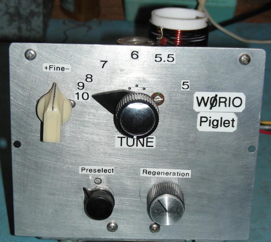
Front view of the Piglet Regen Receiver
(C) 2014-2021, G. Forrest Cook
Front view of the Piglet Regen Receiver
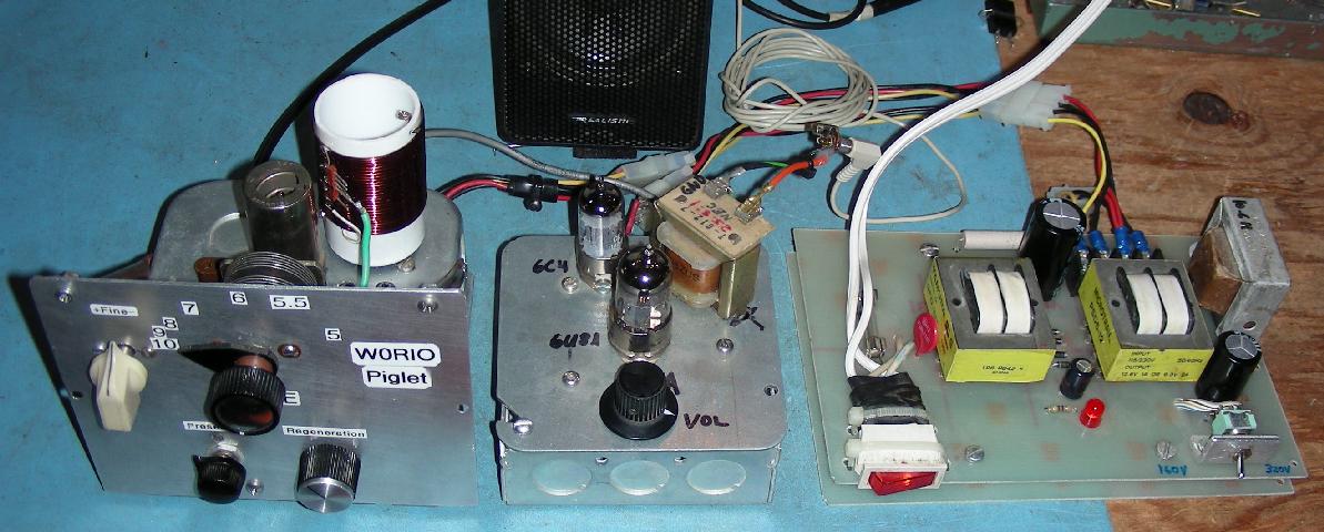
The Piglet Regen Receiver, Audio Amp and Power Supply
|
|
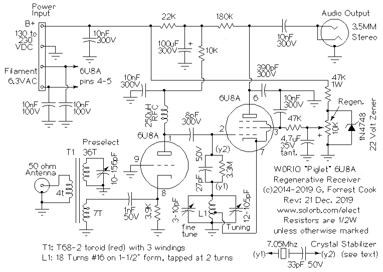
Schematic of the Piglet Regen Receiver
This project is your author's first attempt at building a regenerative receiver, it has gone through several revisions. Thanks go to W9BRD, DF3DL and others for suggestions on how to improve the detector circuitry. The "Piglet" name comes from the squealing sounds that regenerative receivers can make when the regeneration control is adjusted. The receiver tunes from 5-10 Mhz in the shortwave band and it can pick up foreign and domestic AM short wave broadcast stations with ease. One of the design goals of the receiver was to be able to pick up both the 5Mhz and 10Mhz WWV time signals. When propagation conditions are good and the Piglet is connected to a decent outdoor antenna, stations can be picked up from around the world across the entire tuning range of the receiver.
If the receiver is built with a narrow tuning range instead of the broader 5-10 Mhz range, it can be used to receive SSB and CW radio signals in the 40 meter ham band. The receiver could also be set up to cover just one shortwave broadcast segment. With a few minor coil and capacitor adjustments, the receiver should also work on the 80 meter and 30 meter ham radio bands. If lower frequency tuned circuits are used, the receiver should also work in the 550Khz to 1.6 Mhz AM broadcast band and the lower frequency VLF band. If the receiver is used for lower frequency reception, the values of the 8pF and 27pF capacitors located between the two 6U8A sections should be increased.
Regens have always been very popular because they deliver a lot of performance from a small number of parts. Their disadvantages include being rather "tweaky" to adjust, de-tuning from wind on the antenna and a tendency to transmit RF from the receiving antenna while making tuning adjustments. This design fixes the second and third of those issues by using a grounded-grid RF isolation amplifier on the RF input side.
The 6U8A tube includes a triode and a pentode in one 9 pin envelope. Most 6U8A regen designs use the pentode as the detector and the triode as an audio amp. This design uses the triode as a tuned grounded-grid RF amplifier ahead of the pentode detector section. This arrangement isolates the antenna from the detector stage and improves the front-end selectivity of the receiver. All of the audio amplfication is done outside of the Piglet.
The receiver can run on a wide span of B+ voltages, it works between 130VDC and 230VDC, allowing many power supply choices. I used my Power Supply for Vacuum Tube Experiments (set for either 160VDC or 260VDC) to power this project. The supply is sufficient to power both the high voltage and filament supplies for the Piglet regen and the Low Power 6U8A Vacuum Tube Audio Amp V3. When the supply is powering both circuits, the B+ loads down to either 130V or 230V. The higher supply voltage setting gives the receiver more audio output and higher RF gain.
The Piglet's 6U8A tube requires a filament supply of 6.3VAC at 450mA and the V3 Audio amp requires 6.3VAC at 600mA for its 6U8A and 6C4 tubes for a total of 1.05 Amps. The Piglet's filaments can be run on 6.3VDC instead of AC, this can lower the amount of hum heard in the receiver. If you decide to run the Piglent on DC filament power, it is a good idea to use a large filter capacitor and a voltage regulator such as an LM317T in the DC supply to provide a steady voltage.
If you don't want to build the outboard tube amplifier, a pair of stand-alone amplified computer speakers will work nicely with this receiver.
This project involves the use of potentially lethal high voltages including 120 VAC and 130 to 260 VDC. The project should only be taken on by someone who has experience working with high voltage circuitry. The power supply should always be disconnected and the power supply capacitors should be discharged when working on the receiver.
A 10nF 200V bypass capacitor is wired across the B+ line and two 10nF bypass capacitors are wired to across filament pins, these parts bypass any extraneous RF that may be picked up on the power lines to ground.
The triode section of the 6U8A is wired in a tuned input grounded grid amplifier configuration. The 50 ohm antenna input is coupled to the tuned input circuit's T68-2 powdered iron toroid coil via a 4 turn winding. A 36 turn winding and a 10-156 pF variable capacitor form the resonant part of the tuned input circuit which covers just beyond the 5-10 Mhz tuning range of the detector. A 7 turn output winding matches the tuned circuit to the cathode of the grounded grid amplifier through a 1nF DC blocking capacitor. The 3.9K resistor sets the bias level of the grounded grid amplifier and the 250uH RF choke isolates the amplified RF input signal from the B+ supply. The 10K plate resistor and 10nF capacitor further isolates this stage from the detector circuitry.
The output of the RF amplifier is lightly coupled to the pentode detector stage via an 8pF capacitor. The detector's tuned circuit consists of a tapped solenoid coil in parallel with an 12-105pF broad-tuning capacitor and an optional 3-10pF fine-tuning capacitor. The tap point on the L1 oscillator coil can be moved to change the behavior of the regeneration circuit. Placing the tap at 6 turns can cause the circuit to oscillate at around 15Khz if the regeneration control is turned too high. Moving the tap down to 1 turn can reduce or eliminate this issue, but the at the cost of much lower gain. Moving the tap to 2 turns provides a good compromise between sensitivity and stability.
A 3.3M grid leak resistor provides the grid bias and the 27pF capacitor couples the top of the tuning coil to the pentode's grid circuit. These values are not set in stone, but work well across the 5-10 Mhz frequency range. The 27pF capacitor should be increased in value if the receiver is to be used at frequencies below 5Mhz.
The regeneration control provides a variable voltage to the 6U8A pentode's screen grid, it is used to keep the detector circuit just at or slightly below the point of RF oscillation. The regeneration control's voltage is regulated by the 1N4748 22 Volt zener diode, a 24V zener will also work here. Regulation helps to stabilize the behavior of the circuit. The 10K Regeneration potentiometer varies the pentode's screen grid voltage from 0-22V, which spans the region below and above the point of oscillation. The 4.7uF capacitor gives the Regeneration control a smoother response, the 47K resistor between the Regeneration control and the screen grid limits the screen current and the 10nF capacitor bypasses any RF on the screen grid to ground.
The plate circuit of the detector uses a 180K series resistor to pull the plate voltage up to the operating range. Any RF that appears on the plate bypassed to ground via a 390pF capacitor. This capacitor also acts as an audio high-cut filter, the value can be adjusted for more or less treble. The audio output of the detector is fed to the output jack via a 10nF capacitor, where it is fed to a high-impedance input audio amp.
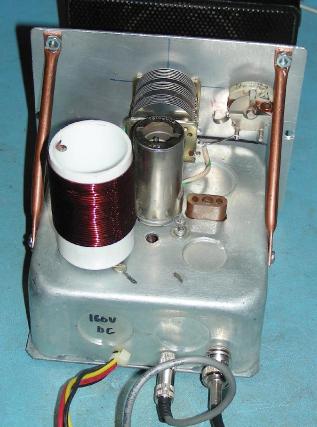
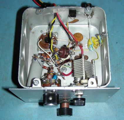
The receiver was built into a 4-1/2"x4-1/2"x2" electrical utility box. An aluminum plate was mounted on the side of the box with some 6-32 screws to serve as the front panel. The 6U8A tube socket and the Octal coil form socket were installed into knockout holes on the top of the box. A solid box cover plate was used for the bottom of the box. Appropriate holes were drilled for the rest of the components. A number of multi-point terminal strips were installed inside the box and components were installed with the point-to-point wiring method. All RF wiring should be kept as short as possible.
The L1 detector coil was wound onto a custom coil form. The form was made by gluing a section of plastic sink drain pipe to the base of an old octal tube. Small holes were drilled in the pipe for the wires to pass through. A matching octal tube socket was mounted to the chassis. The coil tap point was made adjustable by spreading the leads of a 0.1" 5 pin SIP header out and soldering the contacts to different turns on the coil. The tap wire was soldered to a single pin from a DIP IC socket which can be plugged into the various SIP header pins. Since the optimum tap point was found to be at 2 turns, this adjustable tap setup can be eliminated.
The L1 pluggable coil form was originally used with the intention of being able to use different coils for different bands. The circuit design changed during prototyping and the T1 tuned input circuit was added. Transformer T1 could also be bult as a pluggable coil if you want to be able to change bands. For single-band operation, L1 should be built without the plug and socket, this will help with the physical stability of the receiver.
In the first prototype version of the Piglet, the coil form was mounted too close to the 6U8A tube and undesired oscillations would occur with certain tubes. A grounded piece of printed circuit board material was added between the tube and the coil. A further modification of the receiver involved removing the circuit board shield and installing a metallic tube shield around the 6U8A.
Two copper braces were added to mechanically stabilize the front panel against the metal box. The brackets were made from 1/4" copper tubing, the ends were flattened in a vise and drilled to hold the mounting screws.
A well-stocked junk box is the first place to start, your author scrounged most of the parts for this project from discarded electronics. The tuning capacitor came from an old radio and included a built-in gear-reduction drive. If you use a regular variable capacitor, a vernier dial is highly recommended. Tubes and sockets can be found at Antique Electrical Supply or on eBay. Home Depot, or any well-stocked hardware store will carry the electrical boxes and plumbing parts.
Connect an antenna, the power supply and the audio amplifier or amplified computer speakers to the receiver. Be sure to ground the receiver chassis to the AC ground for safety and performance. Apply power to the receiver and let it warm up for a few minutes.
For the antenna, a standard 40 meter ham radio dipole antenna will work well with this receiver, a random longwire antenna can also be used. A resonant antenna such as a dipole will provide the best reception around its center design frequency.
Adjust the Tuning control to a part of the band that you want to listen to. Set the Fine Tuning control to the center of its range. Adjust the Regeneration control until the receiver just starts to hiss. Adjust the Preselect control for the loudest signal, if the receiver starts to squeal, turn the Regen control down a bit. Adjust the Tuning control until you hear a station. Adjust the Fine Tuning control to zero in on the station. At the higher frequency end of the dial, the Fine Tuning control can be used to select individual stations across a small band segment.
All of the controls will interact with each other so it is a bit of an art form to get the receiver tuned to a station and peaked for the best signal. Once the controls are set correctly, the audio quality will be quite good. The Regeneration control will have different optimum settings as the Tuning control is changed across its frequency range. If you tune across a narrow range of frequencies on the shortwave band, such as the 7Mhz or 9Mhz broadcast bands, multiple stations can be selected by just changing the Tuning controls.
When the Regeneration control is adjusted too high, the 6U8A Pentode section has a tendency to break into oscillation at around 15Khz, not all regen circuits behave this way. Numerous changes were tried to eliminate this behavior, including removing the power and connections to the triode stage. The oscillation was found to originate in the 6U8A pentode detector stage. Fortunately, this does not affect the receiver performance as long as the regen control is adjusted correctly.
The initial design of this receiver covers 5-10 Mhz, which includes several shortwave broadcast bands, the 40 meter ham radio band and the 5 and 10 Mhz WWV time stations. With such a wide frequency range, the receiver tuning is very touchy, even with a vernier drive capacitor. If a narrower tuning range is desired, replace the tuning capacitor with a lower-capacitance part and add a fixed-value capacitor in parallel.
This design can be modified to receive frequencies from the AM broadcast band up to around 20 Mhz by changing the resonant frequencies of the two tuned circuits.
The detector coil (L1) is already wound on a plug-in coil form. It would be relatively easy to construct other plug-in coils, just use a similar turns percentage (about 30% from the bottom) for locating the cathode tap. The extra pins on the coil socket could be used to connect the unused tuning capacitor sections for operation on lower frequencies. The preselector coil could also be built with a plug-in form, different types of toroid material and turn counts would be required for coverage of other frequency bands.
If the receiver is to be used to pick up ham radio signals, the tuning range should be reduced to cover a much smaller range, such as 6.9-7.4 Mhz. This can be accomplished by replacing the tuning capacitor with a much smaller value variable capacitor and placing a fixed capacitor across the new tuning capacitor to set the range. It would be also be a good idea to use a gear reduction vernier dial on the tuning capacitor.
An experimental crystal stabilizer was added to the regenerative feedback loop in an effort to stabilize the receiver over a narrow band of the radio spectrum. The results were quite impressive, when the receiver was tuned to near the crystal frequency it suddenly became more sensitive and also more stable. Morse code signals could be copied easily and could be listened to for many minutes without any significant drift.
A large FT-243 ham radio crystal with a nominal frequency of 7.05 Mhz was used. With the crystal installed in the socket, the receiver tuned from about 7.03 to 7.05 Mhz with the sensitivity dropping off on the edges of that range. When the tuning capacitor is adjusted so that the LC circuit resonates with the crystal, one can hear the crystal "pop in" to resonance and the received signals get much stronger. When the crystal is removed from the socket, the receiver goes back to its normal wide-band operation. For crystal-stabilized operation, it would be a good idea to modify the tuning capacitor configuration for single-band operation (see above).
Other options for crystal-stabilized tuning include adding a small coil in series with the crystal, using multiple crystals in parallel and switching several crystals with different frequencies to provide wider coverage. Ceramic resonators are another option, they tend to have a wider frequency pulling range than quartz crystals.
Back to FC's Ham Radio Circuits page.