(C) 2014-2023 G. Forrest Cook
This project extends my 6U8A Vacuum Tube Audio Amp V2 by adding a 6C4 preamp stage for higher sensitivity. The preamp allows the circuit to be used as a low-power guitar amp, a circuit testing amp and an outboard amplifier for small receiver projects. The maximum output power of this amplifier is around 100 milliwatts with a B+ supply of 250VDC.
This version of the 6U8A amp has been used as a module for the House Finch Direct Conversion Tube Receiver, the Meadowlark Direct Conversion Receiver and the Piglet 6U8A Regenerative Receiver.
This device uses high voltages including 120VAC and up to 250VDC. The project should only be taken on by someone who has experience working with high voltage circuitry. The power supply should always be disconnected and the B+ line should be shorted to ground when working on the amp.
Power Input - 6.3VAC@600mA filament and 120-250VDC B1+
Audio Input - 1M Impedance
Speaker Output - 8 ohms, 100mW max at 250V B1+
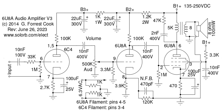
The low-level audio input signal is sent through a 10nF DC isolation capacitor and a 33M grid stopper resistor to the grid of the 6C4 preamp tube. The grid stopper combined with the internal grid capacitance forms a low-pass filter to prevent radio frequency signals from affecting the 6C4. The 6C4 is wired as a class A amp with a 1M grid leak resistor to ground. The output of the preamp goes through a 10nF DC isolation capacitor to the 500K volume control potentiometer.
The output of the 6C4 stage feeds the 500K volume control potentiometer. The wiper of the volume control feeds the grid of the 6U8A triode section which serves as a mid-level driver stage. The 3.3M grid resistor reduces scratchy sounds that can occur when the volume control is turned. The 6U8A triode is wired as a class A amp with a negative feedback connection on the cathode.
The output of the driver stage is sent to the control grid of the 6U8A pentode section via a 10nF DC blocking capacitor. The pentode is wired as a class-A amplifier with a transformer output. The negative feedback loop uses a 120K resistor and 470pF capacitor from the speaker side of the output transformer to the cathode of the 6U8A triode driver stage. The NFB loop helps to keep the amplifier response linear, feedback is kept at a fairly light level to preserve the amp's dynamics.
The R/C network across the output transformer primary acts as a lowpass filter and helps to reduce high voltage transients on the plate circuit. The pentode's screen grid is pulled up to the B1+ voltage through a 3.3K current limiting resistor and is AC-bypassed with a 10nF capacitor. The screen current varies between 1.5mA and 4.5mA depending on the B+ voltage and the output signal level.
Power to the amp comes from my Power Supply for Vacuum Tube Experiments, which can be set for either 160V or 320V DC output. The amplifier loads the supply voltage to either 135VDC or 250VDC. The B1+ supply goes through two more RC filter stages to produce B2+ and B3+, these filters progressively reduce the power supply hum and isolate the three amp stages from each other.
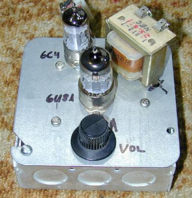
The amplifier was built onto a standard 4"x4" electrical utility box cover plate. The plate was the type with a conduit knockout in the center. The knockout was removed and two small holes were drilled on either side to hold the 9 pin 6U8A tube socket. A second hole was drilled and filed to fit the 7 pin 6C4 socket. Several 5/32" holes were drilled in the box cover plate to hold the terminal strips.
A hole was drilled in the top of the box to hold the volume control potentiometer. The potentiometer could also be mounted on the front of the box. The various resistors and capacitors were connected between the tube socket and terminal strip pins. A standard Romex style cable clamps was used on the utility box for securing the power supply wiring and coaxial audio input cable. A 3.5mm miniature audio jack (not shown in the photo) was added to the top of the box cover to act as an audio input.
It is possible to replace the 6C4 triode with half of a common 12AU7 dual-triode. The 12AU7 filaments can be wired so that only one side is powered, doing this will prevent wasted power and unnecessary heat.
Connect an 8 ohm speaker to the amp's output and plug an audio source into the input. Apply power and turn the volume control up to the desired listening level. The amplifier can also be used for powering low impedance mono headphones, two of the amps could be used for powering stereo headphones. This amp has been used with several different radio receiver front ends for many years and continues to work nicely. It has also been used as a general-purpose utility amp for troubleshooting audio circuitry.
Back to FC's Music Circuits page.