(C) 2017, G. Forrest Cook
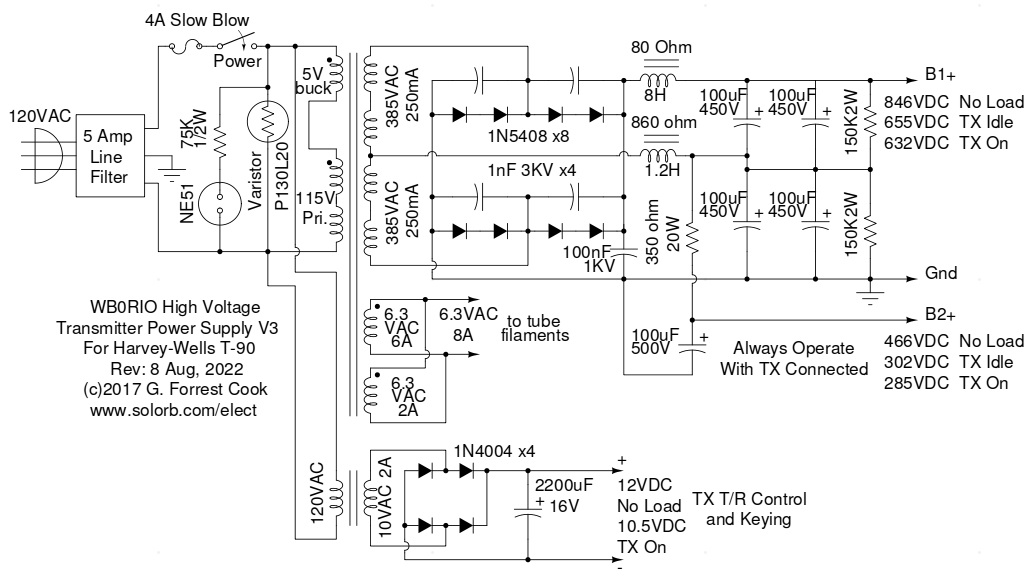
This project involves the construction of a modular high voltage power supply that is designed for powering a Harvey Wells T-90 Transmitter. The supply was designed as a general-purpose device and it is suitable for powering other transmitter projects. The supply produces 6.3VAC for running tube filaments, 300VDC for powering transmitter driver stages and 650VDC for powering a transmitter final amp. The supply includes a 12VDC output for powering auxiliary control circuitry.
The power transformer used in this project was originally scavanged from a large 1960s vintage black and white television set. Similar transformers may be used for this circuit, the output voltage and current ratings will vary depending on the transformer used. This power supply was built using many surplus components, including the transformers and chokes. New rectifier diodes and filter capacitors were used in the circuit to ensure reliability.
The supply will allow the Harvey-Wells T-90 transmitter to produce around 75 Watts of RF output power. This is close to the maximum output power for this transmitter. It is a good idea to install a small fan on the transmitter case over the 6146 final amplifier tube to insure cool operation.
The energy efficiency of this power supply is good for tube technology. The lack of rectifier filaments and the use of a transformer primary buck winding reduce the average power usage. After powering the T-90 for an hour-long Morse code QSO, the power transformer remains only warm to the touch.
This project involves the use of potentially lethal high voltages including 120 VAC, 770VAC and up to 850 VDC. The project should only be taken on by someone who has experience working with high voltage circuitry. Always disconnect the power cord and discharge all of the high voltage capacitors before working on a high voltage power supply.
The power supply is a modified version of the "Economy Power Supply" featured in the ARRL handbooks. It produces around 300VDC for the driver side of the transmitter, around 650VDC for the power amplifier tube and 6.3V at 8A for the tube filaments. The accessory unregulated 12VDC power supply is used for powering the transmitter's T/R and keying circuitry.
The AC input power is routed through a 5A line filter, this keeps line noise from getting into the power transformer and also prevents stray RF power from getting back to the power line.
The primary side of the power transformer uses the 5V rectifier winding in a buck-mode to reduce the secondary voltages by a few percent. This modification allows older 115V transformers to produce the correct filament voltages when they are run on 120V mains. The 130V varistor on the transformer primary provides the first stage of protection against transient voltage spikes that may come in on the power line. Spikes can be multiplied by the transformer and may damage the rectifier diodes. A neon bulb pilot light in series with a current limiting resistor are connected across the transformer primary.
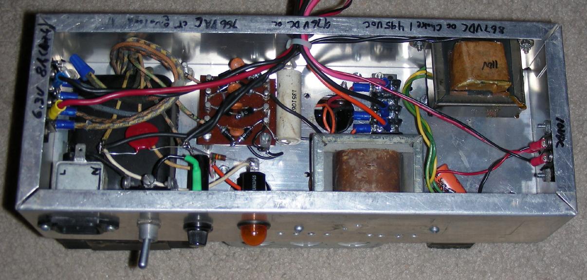
The power transformer has a 770V/250mA center-tapped high voltage winding that drives a bridge rectifier and feeds a choke-input LC filter for the 650VDC output. The 1nF capacitors across the rectifier diodes prevent transient voltage spikes from damaging the diodes. The 100nF/1KV capacitor on the output of the bridge rectifier helps to filter out any high frequency line noise that makes its way through the transformer.
The center-tap of the transformer is filtered by a 1.2H choke and then feeds the center of the high voltage capacitor bank. The 1.2H choke between the transformer center-tap and the center of the capacitor bank provides DC filtering for the 300VDC supply. The choke also lowers the voltage on the center of the capacitor bank. The capacitor bank center is routed through a 350 ohm resistor and across a 100uF capacitor to provide the filtered 300VDC B2+ output. The 100uF B2+ filter capacitor is rated at 500VDC since this rail can reach around 466VDC with no load connected.
A pair of 150K 2W resistors are connected across the HV output to act as a minimum load and a safety discharge load.
The 12VDC DC power supply uses a separate power transformer. The 10VAC output feeds a bridge rectifier which is followed by a large filter capacitor, this combination produces unregulated 12VDC power.
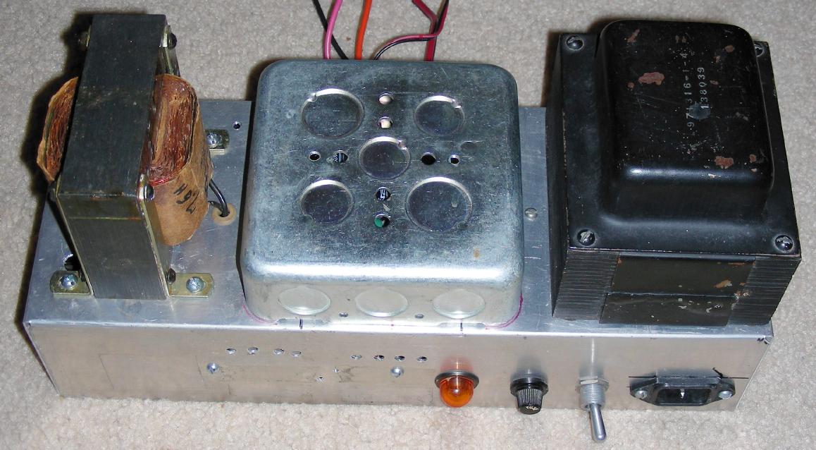
All of the components were mounted on a 13"x5"x3" aluminum box. The transformers and chokes were spaced apart from each other and mounted at right angles where possible to minimize magnetic interaction. The HV bridge rectifier circuit was wired on a multi-point bakelite terminal board and that was mounted inside of the chassis on spacers to minimize the chance of high voltage arcing and breakdown. All of the high voltage connections were rounded and smoothed with plenty of solder, sharp points can bleed HV and cause arcing.
A capacitor "dog house" was built by mounting an inverted 4"x4" electrical utility box on top of the main chassis. All of the capacitors are installed inside this box on terminal strips.
The various output voltages are connected to screw-type terminal strips using crimp terminals. The high voltage terminal strip has a solid bottom, this helps to prevent arcing to the chassis. The output wires exit the cabinet through a large rubber grommet. Appropriately rated wire should be used for connecting the two high voltage outputs to the transmitter.
Operation of the transmitter power supply is fully automatic. Just turn it on, tune up the transmitter and start communicating with other radio Hams.
Back to FC's Ham Radio Circuits page.