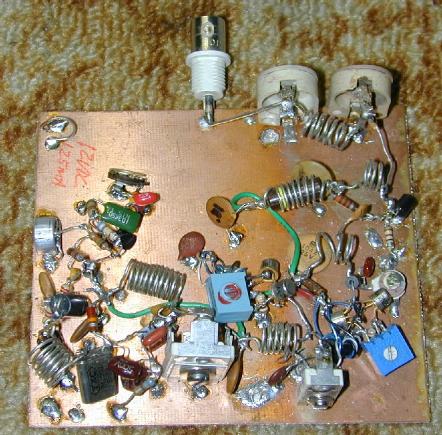
Dead-bug construction of circuit on blank circuit board material.
(C) 2010-2013, G. Forrest Cook (W0RIO)
Dead-bug construction of circuit on blank circuit board material.

After constructing my Solar Powered FM Bug circuit, I decided that a big improvement would involve building a bug with a more frequency-stable transmitter. Numerous Variable Crystal Oscillator (VXO) circuits have been published for ham radio receivers and transmitters, these are normally used for CW (Morse code) applications in the 3-30 Mhz HF ham radio bands.
VXO circuits use a variable capacitor or inductor in a crystal oscillator circuit to pull the oscillator frequency above or below the crystal's specified frequency. VXOs are inherently frequency-stable, thanks to the crystal. This circuit was the result of experimentation in using a varactor diode (voltage variable capacitor) in the VXO circuit to modulate the oscillator's frequency with an audio signal for frequency modulation (FM).
The frequency deviation of a VXO is relatively small, and most inexpensive crystals resonate at frequencies below 30Mhz. Quadrupling the 24Mhz base frequency with frequency doubler circuits also results in a quadrupled frequency deviation. I used MV1401 varactors because I had some of them in my parts collection. It might be worthwhile to try different varactor diodes. Another trick that is commonly used for producing a wider VXO frequency swing is to use two or more of the same frequency crystals in parallel.
Varactor diodes have a non-linear change in capacitance versus control voltage, this causes a non-linear frequency deviation and resulting distortion of the modulation signal. Keeping the deviation small reduces this effect. It should be possible to incorporate a non-linear op-amp circuit to counteract the diode's response, however the circuit works fine when used as a low powered transmitter.
The cascaded frequency doubler sounded like a fairly straightforward circuit to design, but actually making it work took a number of attempts and many circuit modifications. The book Solid State Design for the Radio Amateur by Wes Hayward (W7ZOI) and Doug DeMaw (W1FB) provided some excellent background on transformer-based frequency doubler circuits that operate in the VHF range.
A common 24Mhz microprocessor crystal can have its frequency quadrupled to produce a 96Mhz signal, this is right in the middle of the FM broadcast band. Other common crystals in the range of 22-27Mhz can be used to produce signals in other parts of the FM band, common crystal frequencies include 24.0, 25.0, 26.0 and 27.0 Mhz. Variations on this circuit could be used to produce signals on amateur radio bands such as 50 Mhz and 144Mhz.
Note that modern digital-tuned FM broadcast receivers only cover 200Khz steps such as 95.9 and 96.1Mhz, if you want the transmitter to work on a regular FM frequency, it may be necessary locate a crystal which has a value that falls on a standard broadcast frequency after quadrupling. An analog receiver is not restricted to preset frequency channels and is a good choice for receiving the 96 Mhz signal. The transmitter will be much more effective if you use a frequency that is not too close to that used by any high-powered local stations.
The Electret microphone is biased with a 15K resistor, the resistor value may need to be changed to optimize the gain and noise for your particular electret mic. The microphone signal is coupled to the 2N3904 transistor through a 10nF DC blocking capacitor. The value of this capacitor can be increased if more bass is desired.
The microphone signal is amplified by a 2N3904 audio amplifier. The audio signal is DC isolated with a 100nF capacitor and RF-bypassed with a 390pF capacitor. The two 220K resistors provide a 6V nominal bias for the MV1401 varactor diodes, the audio signal shifts the bias voltage above and below 6V to change the varactors' capacitance. The varactor capacitance shifts the 24MHZ crystal oscillator's frequency to produce frequency modulation.
The crystal oscillator circuit uses the Colpitts configuration. L1 and the two capacitors connected to the 2N2222A collector form a circuit that resonates at 24Mhz. A careful observer may note that the two capacitors are grounded, but L1 is connected to +12V, the 100nF capacitor on the upper side of L1 shorts RF on the +12V line to ground, so the the coil and capacitors are effectively a parallel resonant circuit. Grounding the variable capacitor provides a better physical mounting.
The 24Mhz RF signal is coupled to T1 via a 300pF DC blocking capacitor. T1 is an Amidon T50-6 toroid core with a trifiliar winding. T1 and the two 2N2222A transistors form an active doubler circuit. The 33K resistor on the toroid provides base bias for the transistors and the 10nF capacitor provides an RF path to ground for the T2 secondary center tap. One transistor conducts on the positive half of the 24Mhz wave and the other conducts on the negative half of the wave. The two signals are effectively OR-ed together to produce a 48Mhz signal. The collector side of the two transistors has a tuned circuit that resonates at 48Mhz so that the stage produces a pure sine wave with minimal harmonics.
The output of the first active doubler is tapped off of the output coil and fed to the next active doubler. The second active doubler is essentially the same as the first, except that it converts 48Mhz to 96Mhz and its output is tuned to 96Mhz. An Amidon T30-10 powedered iron toroid core was used for transformer T2, it is important to use this type of core material for proper operation at this frequency.
The 96Mhz output from the second active doubler is fed to the final 96Mhz tuned amplifier stage. The output of the final amp is DC-bypassed through a 1nF capacitor and fed to the antenna via a pi output section consisting of L5 and the two trimmer capacitors.
Note that the power amplifier outputs around 2.5mW, which is well under the 100mW legal limit for the US.
Note that the power amplifier outputs more than 100mW of RF, 100mW is the legal limit in some countries such as the US. The output power can easily be reduced by increasing the value of the 100 ohm resistor on the emitter of the final amplifier.The prototype circuit was built using the "dead bug" construction method, grounded parts were soldered to a blank copper circuit board and connections were soldered between the parts as required. Keep all leads as short as possible since this circuit operates in the VHF range. A custom circuit board could also be designed.
A 100Mhz or faster oscilloscope with a 10x probe is recommended for aligning this circuit. A spectrum analyzer is even better if you have access to one. Keep in mind that at 48Mhz and 96Mhz the scope probe will have a significant effect on the displayed waveform. When properly adjusted, the nearest harmonics should be more than 40db below the 96Mhz signal.
Center the two balance trimmers on the doubler circuits. Connect the scope to the 24Mhz VXO collector pin and adjust the stage's peaking control for the largest sine wave. Connect the scope to the collectors of the 48Mhz active doubler and adjust the next peaking conntrol for the largest and most symmetrical sine wave. Connect the scope to the collectors of the 96 Mhz active doubler and adjust the stage's peaking control for the largest signal. If the balance trimmer causes the output signal to significantly drop when it is in the center of its range, you may need to reverse the phase of one of the toroid output windings.
Connect a 50 ohm resistive load to the antenna terminals and connect the scope's 10x probe across the 50 ohm load. Adjust the 96Mhz tuned amp's peaking control for the largest sine wave. The output level can be optimized by squeezing or expanding the turns of inductors L4 and L5. Adjust the two trimmers across L5 for the highest signal. Re-adjust the 48 Mhz and 96 Mhz peaking controls and the two balance trimmers for the largest and most even output waveform.
The modulation control should be adjusted for the the loudest received signal below where any audible distortion can be heard.
Apply 12VDC to the circuit, tune the signal in with an analog dial FM receiver and listen to whatever the microphone picks up. Use resonant antennas for both the transmitter and receiver for the best results. This circuit takes a fair amount of current to operate. If you want to power the bug from a battery, use a 3 to 7 amp-hour lead-acid gell cell for a reasonably long operating time. Be sure to include the fuse between the battery's + terminal and the transmitter.
It is easy to replace the condenser microphone with another audio source such as a CD player, just remove the microphone and its pull-up resistor and feed the audio signal into the 100nF capacitor that feeds the base of the 2N3904 transistor. If you keep the audio signal in the "sweet spot" where it is large enough to modulate fully but small enough that it doesn't clip, the transmitter's fidelity can be quite good.
Back to FC's Micro Power FM Broadcasting page.