(C) 2008, G. Forrest Cook
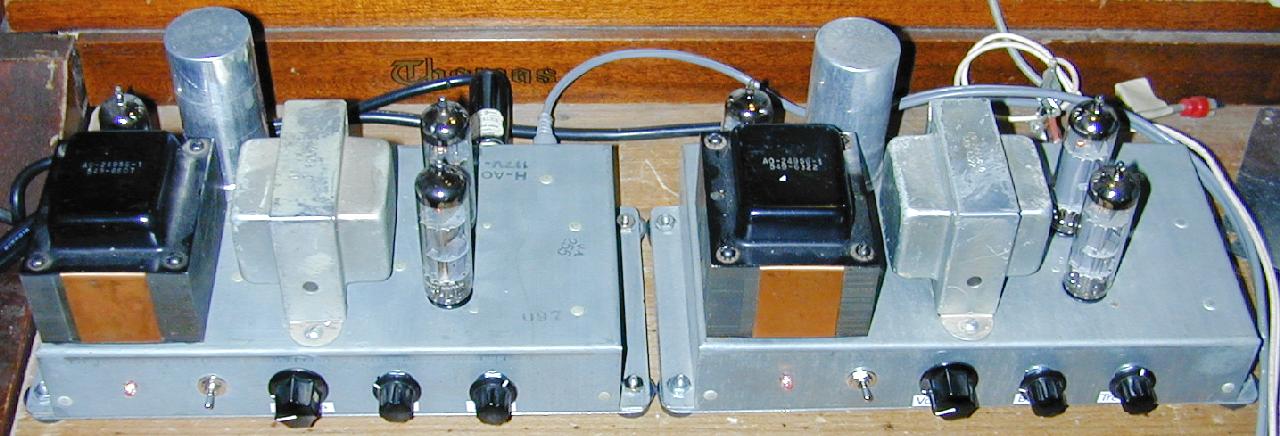
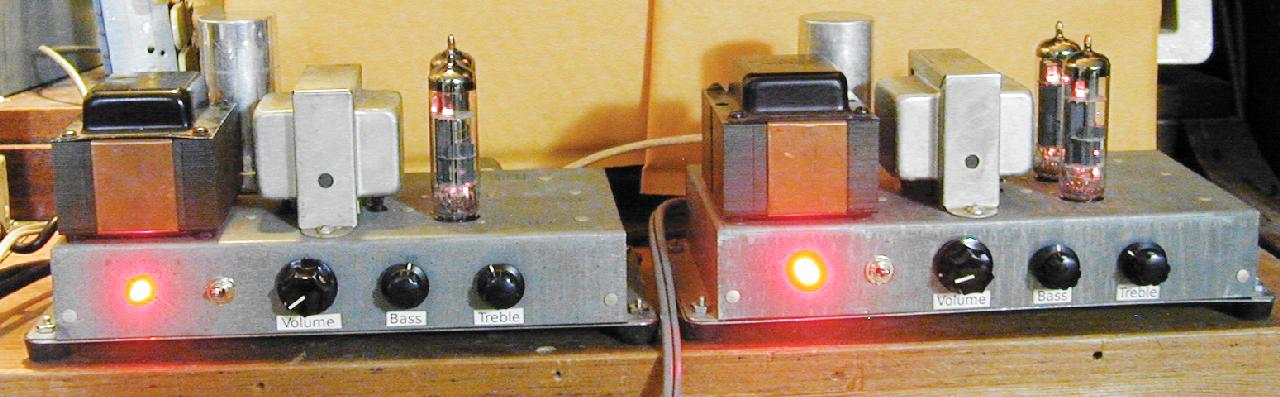
The Hammond AO-44 reverb amplifier was designed to be used an a secondary reverb channel amp in Hammond A-100 and M-series organs. The AO-44 amps can be found for reasonable prices on eBay. These units can easily be converted into a mono tube amplifier that is suitable for use as one channel in a stereo amp, aka a monobloc amp. The audio power output of this amp conversion will be around 8 watts.
With a little more effort, the AO-44 chassis can also be turned into a higher power guitar amplifier that uses a pair of 6BQ5/EL84 pentodes and a 6U10 triple triode compactron tube. See the Spartacus Amp project for details. Also, see the Spartacus Max project for a higher-power combination guitar and monoblock amp that uses the larger Hammond AO-35 chassis.
This is a non-trivial project. It takes a lot of technician skills to deconstruct and reconstruct the amplifier circuitry. Also, there are plenty of lethal high voltages inside of this amp including 120 VAC and 300 VDC. The project should only be taken on by someone who has experience working with high voltage circuitry. The power should always be removed when working on the amp, the circuitry is designed to discharge the capacitors when power is removed, but it's always a good idea to short out the electrolytic capacitors before working on the amp.
AC Power Input - grounded 120VAC, 40 Watts
Input - High Impedance (1M ohms)
Speaker Output - 8 ohms, 8 Watts
On/Off switch
Input Volume
Bass
Treble
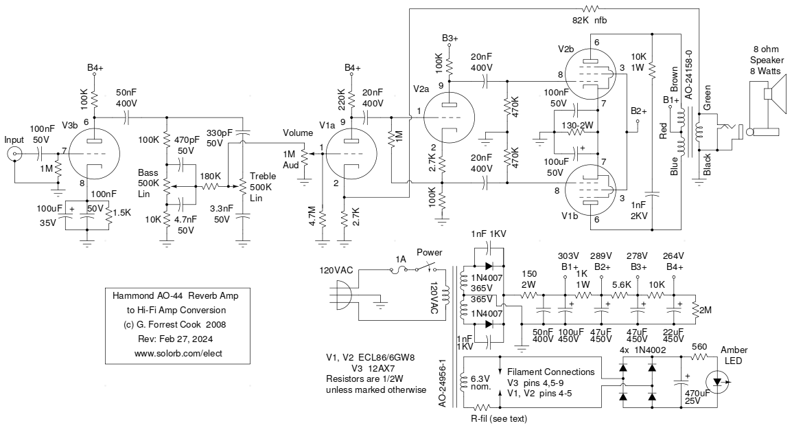
The original Hammond AO-44 amp design is intended to have its input connected across the speaker output of the main organ power amp. There is a volume normalization circuit that uses a pair of small light bulbs and a fairly hissy preamp stage involving an ancient germanium transistor as the first stage. All of these components need to be removed. The 6X4 rectifier tube wiring should be completely removed and replaced with a pair of 1N4007 rectifier diodes and a 150 ohm 2 Watt resistor, these parts are mounted on a new terminal strip. The 6X4 socket is now available for use by the 12AX7 preamp tube, this gives the amp an all-tube signal path. The speaker output wiring can be moved to a 1/4" jack for convenience. With the exception of the new output tube cathode capacitors, the majority of the wiring on the two ECL86/6GW8 tubes is left alone.
The audio input comes from the existing RCA jack on the back of the amp, it is routed though a small length of coax wire and is fed through a 100nF DC blocking capacitor to the grid of V3b. V3b is one section of a 12AX7 dual triode that is wired as a standard class-A amplifier. The other half of V3 is not used. The cathode circuit of V3b uses two capacitors (100uF and 100nF) in parallel, the small capacitor improves the high frequency response of the circuit. It is possible to substitute a 12AT7 (lower gain) or a 12AU7 (even lower gain) for V3 if one wishes to adjust the total gain of the amp. If a 12AT7 is used, the cathode resistor should be increased to 2.7K.
The output of V3b is fed into a Baxandall tone stack which gives a boost and cut response for both bass and treble. The output from the tone stack is fed through the volume control into V1a, another class-A amplifier stage. The 4.7M grid leak resistor on V1a pin 1 is in parallel with the series combination of the 180K resistor, the 500K bass control and the 10K resistor, it eliminates scratchy sounds that can happen when the volume control is rotated.
Almost everything to the right of the volume control is the stock Hammond AO-44 circuit. Negative feedback is routed from the speaker output to the cathode of V1a to lower the overall gain of the power amp. V2a is wired as a phase inverter, the two phases of the audio signal drive V1b and V2b. V1b and V2b are wired as a cathode-biased push-pull pentode amplifier. The 10K/1W resistor and 1nF/2KV capacitor form a high-cut circuit that cancels out RF oscillations in the output stage.
The power supply high voltage circuit uses a standard center-tapped full wave rectifier fed into an R-C totem-pole network. The 150/2W resistor is used to bring the B+1 down to 303V, which is similar to the voltage provided by the original 6X4 rectifier tube. The 50nF capacitor across the 100uF capacitor on the B1+ line is used to improve the transient response of the output tube plate circuit. The 2M resistor across the B4+ line is a safety feature, it discharges the power supply capacitors when the AC is turned off.
All of the tube filaments are powered by the 6.3V transformer winding. Since only half of V3b is used, it is possible to provide filament power to only one half of the 12AX7 tube to save a bit of power, use pins 5 and 9 instead of pins 4/5 and 9 on the 12AX7. Keep in mind that most 1960s era tube equipment was designed to run on 110 to 117 VAC power and modern power voltages can be as high as 125V. This causes the filaments to run at around 7.5VAC, which can shorten the life of the tubes. An easy way to fix this problem is to put a low value resistor in series with either leg of the transformer's filament winding. A resistor of around 1/2 to 1 ohm at a few Watts should be about right.
The (optional) LED pilot light circuitry consists of four 1N4002 diodes wired as a bridge rectifier across the 6.3VAC filament circuit. The 470uF capacitor produces filtered DC, the 560 ohm resistor is wired as a current limitor in series with a high brightness amber LED. A small 6.3V pilot light bulb could be used instead of the rectifier/LED circuit.
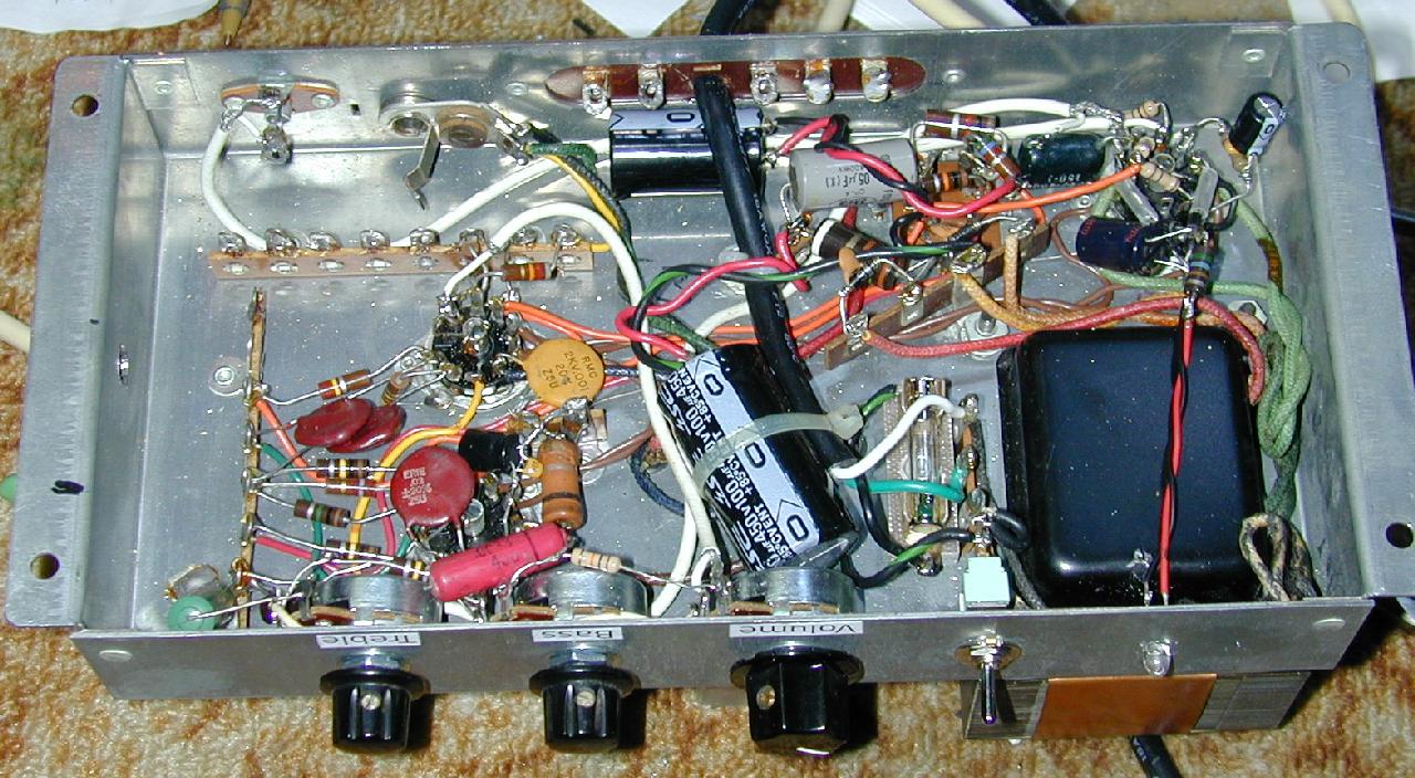
Parts of the original amp wiring should be removed to make room for the new components. Before adding the new circuitry to the amp, it is a good idea to drill all of the new holes in the chassis. Holes should be added for the output jack, the power switch and control pots, the optional LED and the power cord. The power cord was installed in a 1/4" hole that was (carefully) drilled in one of the positions of the six pin wiring connector. It is important to use coaxial wire (white wires in the above photo) for all of the audio signal paths in order to prevent oscillations and noise pickup. All of the tone control components are wired directly to the two tone pots.
It is a good idea to verify the value of all of the resistors resistors in the amp. Replace any bad resistors, these may have drifted way out of tolerance during the decades of use. Old resistors tend to increase in value. The power supply dropping resistors on the bottom of the electrolytic capacitor should be checked and replaced if necessary. Be sure to check the 10K 1W resistor that is across the output transformer.
The original electrolytic filter capacitors are around 50 years old and have probably dried out and lost some or most of their capacitance. New electrolytic capacitors can be soldered across the pins at the bottom of the original capacitor, however it is better to just disconnect the original capacitor pins completely since the caps can short out and potentially damage the power transformer. New electrolytic caps should eliminate any hum that the amp produces. Hum that is caused by defective electrolytic capacitors will be audible in the speakers when the volume control is turned down.
If your AO-44 chassis does not come with a bottom plate, it is easy to fashion a new one by cutting out a piece of galvanized sheet metal with tin snips. The bottom plate should have holes drilled in the corners, rubber feet and 6-32 screws and nuts can be used to attach the bottom plate to the chassis. Rubber feet should be installed on the four mounting screws. Be sure to file the sharp edges of the sheet metal smooth to prevent cuts.
The 12AX7 preamp tube was chosen so that it could use the vacated 6X4 rectifier socket. This saves a lot of metal work. The down side is that this socket is close to the power transformer and the tube will pick up a small amount of hum. Also, half of the 12AX7 is unused. A better solution would be to drill another hole on the other side of the chassis and add a new tube socket and tube.
A 7 pin 6C4 triode (lower gain, like 1/2 of a 12AU7) or a 7 pin 6AV6 (higher gain, like 1/2 of a 12AX7) would both be good choices for the preamp tube. The 6AV6 should be hand-selected for low microphonics. 6AV6 tubes were mass-produced for AM radios in the 1960s and are still available for low prices, but their quality can vary a lot.
Adding a new preamp tube socket would also allow the original 6X4 rectifier to be left in place for those who wish to trade power efficiency for more glowing filaments. Keep in mind that the amp will generate a lot more heat with the 6X4. The 6X4 will also cause the power transformer to run hotter, which can shorten its life. Finally, the rectifier tube will require occasional replacement while the 1N4007 diodes will last a very long time.
Connect an 8 ohm speaker to the output of the amp and connect the input to a line level source such as a CD player or computer audio card's line output. Plug the amp into the power line, turn it on and adjust the controls for the desired sound. Enjoy the warmth and clarity of a tube amp.
These amps have been running reliably for several years, the only issue that has come up has been a scratchy sound when the tubes were moved in their sockets. This was easily remedied by spraying some de-oxit spray on the tube and socket pins, be sure to wipe the residue off of the pins with a tissue. If the controls make scratchy sounds when you turn them, spray a small amount of fader lube into the pots and turn them back and forth a few times until they become quiet.
Back to FC's Music Circuits page.