(C) 2010-2021 G. Forrest Cook
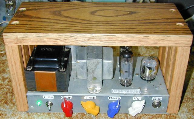
Spartacus amp front view
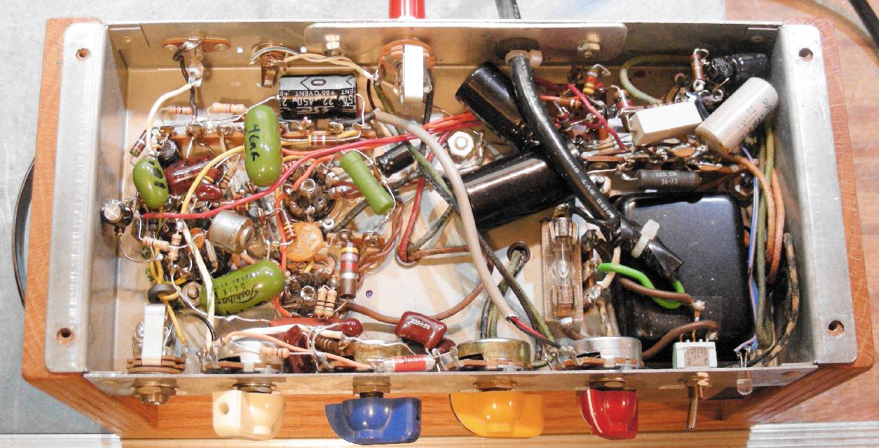
Spartacus amp interior view, click for a larger image.
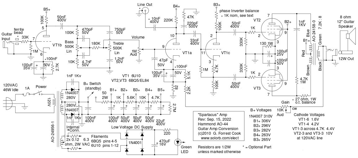
Spartacus amp schematic
The Spartacus project involves converting a Hammond AO-44 organ reverb amp chassis into a push-pull guitar amplifier that uses only three tubes. The AO-44 amps were originally used in Hammond M-103 organs for powering the reverb channel. The output power of this amp is around 12 Watts, which is perfect for a practice and recording amp. The Spartacus amp can get quite loud and the somewhat large Hammond output transformer provides great bass response. The straightforward circuit produces very little hiss and hum.
A cool-looking 6U10 compactron triple triode is added to the amp's chassis, it provides the first two gain stages and the phase inverter stage. A number of circuit tweaks have been added to make it a high-fidelity amplifier. The Spartacus amp is small, light weight and relatively power-efficient for a tube amp.
The Spartacus amp can be contrasted with my Hammond AO-44 Reverb Amp to Hi-Fi Amp Conversion project. The goal of this project is somewhat different. The Spartacus amp has more gain and higher output power, making it better suited for use as a guitar amplifier. Unlike the Hi-Fi amp project, the Spartacus amp involves a complete rewire of the Hammond AO-44 chassis. The rare and expensive 6GW8/ECL86 tubes in the original AO-44 amplifier have been replaced with common and higher power 6BQ5/EL84 tubes. A similar but higher-powered project is the Spartacus Max, which was built on an AO-35 chassis and uses 6L6 or 5881 output tubes.
The name "Spartacus" was inspired by the slave who broke free from the ancient Romans and wreaked havoc on the empire for many years. The amp makes an excellent stereo guitar slave amp when used in conjuction with pitch-shifting vibrato amps such as the Hammonator 2RVT and the Lil' Tiger. Like its namesake, the Spartacus amp can break free and function as a stand-alone amp, it is a good match for 8", 10" and 12" guitar speakers.
The Hammond AO-44 amplifier chassis can be found on eBay for reasonable prices. The Spartacus design is simple and clean. The wiring is a bit dense, but the amp is not overly difficult to assemble. The controls include the basic volume, bass and treble adjustments as well as a gain control.
The gain control (adjustable negative feedback) is more than just a second volume control. It adjusts the the character of amplifier's sound from a compressed and tight jazz amp sound to a punchy and loud sound that is similar to the popular Fender 5E3 Tweed Deluxe amp. In other amps, adjustable gain controls are sometimes labeled "presence" or "loudness".
This is a fairly high-level project. It takes advanced technician skills to deconstruct and reconstruct the amplifier circuitry. Also, there are plenty of lethal high voltages inside of this amp including 120 VAC and >300 VDC. The project should only be taken on by someone who has experience working with high voltage circuitry. The power cord should always be removed when working on the amp, the circuitry is designed to discharge the capacitors when power is removed, but it's always a good idea to short out the electrolytic capacitors before working on the amp.
Power Input - Grounded 120VAC
Guitar Input - High Impedance
Speaker Output - 12 Watts at 8 Ohms
Power On/Off switch
Standby switch (optional)
Volume
Bass
Treble
Gain
The guitar input jack feeds into VT1b through a ferrite bead and a 33K grid stop resistor, these parts both reduce sensitivity to radio frequency interference. The single high gain triode section in the 6U10 which is wired as a class A stage. The 100nF cathode capacitor in parallel with the 100uF cathode capacitor improves the high frequency response. The preamp output drives a Baxandall tone stack, which feeds into the volume control pot.
The output of the volume control drives VT1a, a low gain triode section in the 6U10. VT1a acts as a gain stage and summing point for the Gain control's negative feedback signal. The 47pF capacitor on the grid of VT1a and the 47K/220pF network on the plate of VT1a attenuate signals that are above the hearing range. High frequency energy can create bad-sounding distortion in the output stage.
The output of VT1b feeds VT1c, a low gain triode section in the 6U10. VT1c is wired as a floating cathode (cathodyne) phase inverter. The two out of phase signals from the phase inverter drive VT2 and VT3, the 6BQ5/EL84 pentodes. The pentodes are wired in a push-pull configuration and drive the output transformer. The 6BQ5/EL84 pentodes are configured with a fixed-bias cathode arrangement.
The configuration of the power amplifier (VT1a, VT1c, VT2 and VT3) is similar to the Hammond AO-43 amp that was used in the Lil' Tiger amp. Some of the cathode bias and plate resistors were changed to accomodate the different gain characteristics of the 6U10 triodes compared to the AO-43's 12AX7 triodes.
In the power supply section, the transformer high voltage winding is sent to a center-tapped full wave rectifier consisting of two 1N4007 diodes with protective 1nF capacitors. The high voltage DC is dropped through a totem-pole array of resistors and capacitors to produce the voltages used in the amp. The 50 ohm resistor simulates a rectifier tube's internal resistance and removes a bit of sharpeness from the amp's sound, the original 6X4 rectifier would typically have a larger equivalent resistance. My Vacuum Tube B+ Delay circuit can be used in place of the optional standby switch for automatic power-on sequencing. The standby switch or B+ delay circuit can help to extend the lifetime of the tubes.
A pair of 0.12 ohm, 2W series resistors are used to drop the filament voltage down to a perfect 6.3V. These resistor values may need adjusting depending on your particular line voltage. The two resistors keep the filament voltage balanced around the grounded 6.3VAC center-tap for the best hum rejection. Note that this center-tap ground connection is attached to the grounded high voltage center-tap inside of the power transformer. A single 0.25 ohm/3W resistor on either leg of the filament transformer winding could also be used, that configuration may cause a slight increase in the amp's hum level. Low-value resistors can be made by putting different numbers of common 0.47, 1 or 2.2 ohm, 1/2W resistors in parallel, four 0.47 ohm resistors in parallel would make around 0.12 ohms.
The 6.3VAC filament supply is rectified by four 1N4001 diodes and filtered by a 470uF capacitor to produce around 7.5VDC. The DC voltage drives an emerald green (505nm) LED via a 220 ohm current limiting resistor, the filtered DC voltage insures that the LED does not flicker. A standard incandescent pilot light could also be used instead of the DC supply and LED. Alternatively, a neon pilot lamp in series with a 75K ohm current limiting resistor could be wired across the primary side of the power transformer.
With the exception of the filament and ground wiring, almost all of the original AO-44 circuitry should be removed. The bakelite terminal plate on the back of the amp should be drilled out and replaced with an aluminum plate. Drill holes in the plate for the speaker output jack and AC power wire. The AC power wire goes through a protective rubber grommet and is secured to the plate with zip ties on both sides. Holes were drilled in the chassis for the 6U10 compactron socket (12 pin), the four potentiometers, the input jack, the power switch and the LED.
The 120VAC wiring requires the addition of a chassis-mounted fuse holder, a terminal strip and a power switch. The 1N4007 diodes can be wired to the back of the 6X4 rectifier tube socket or placed on their own terminal strip. The original metal can electrolytic capacitor is not used, it can be left in place for looks or removed and replaced with a metal plate or a metal hole plug.
Two conductor coaxial wire was used for the gain control pot's wiring. Only one end of the coax shield should be grounded to eliminate ground loop hum. The AO-44 amp has a bare ground wire that links the ground pins on the tube sockets and terminal strips together with the capacitor and transformer center tap from the power supply. This ground should be extended to any additional terminal strips and the guitar/speaker jacks.
The majority of the amplifier wiring was done in a point-to-point fashion between the tube sockets and the nearby terminal strips. One of the original terminal strips was left in place and the original parts were unsoldered. A second original terminal strip was removed to make room for the 6U10 socket, a smaller terminal strip was installed in one of the vacated screw holes. The tone stack resistors and capacitors were mounted directly to the back of the tone stack potentiometers. All of the wiring should be kept as short as practical, especially connections to the tube grids and the tone stack.
A wood case was constructed by sawing three pieces of recycled oak flooring to size using a table saw. A piece of galvanized sheet metal was cut to size for the bottom plate using tin snips, the four mounting holes were marked and drilled out. Be sure to file and sand all of the sharp metal edges so that you don't cut your hands on any part of the amp. Stick-on rubber feet were applied to the corners of the bottom sheet to prevent scratching. Screw-mount rubber feet could also be mounted on the four case screws. A carrying handle was added to the right side of the wood case. The wood case doubles as an amp cradle, allowing one to work on the underside of the amp without damaging the tubes.
Plug the amp into a guitar speaker. Plug an electric guitar into the input. Turn the power switch on, let the tubes warm up, then turn the standby switch on if it is included in the amp. Adjust the knobs for the desired tonal quality. Play your guitar. Enjoy the "spartacular" tube sound! The Fuzznikator push-pull tube distortion circuit makes a nice companion for this amp.
The first six of the following variations have been added to this amp, they can be considered as optional changes. The filament voltage reduction modification is highly recommended.
The AO-44 amplifier was designed when AC mains voltages were 110/115/117V. Mains voltages are now typically 120V or more. This can cause the 6.3VAC filament voltages to rise as high as 7.5VAC, causing excessive tube heating and shorter life. The 6BQ5/EL84 and 6U10 filaments draw around 2.2A at 6.3V. With a 125VAC line input voltage, the filament voltage was around 7V. The filament voltage can be reduced to the correct 6.3VAC by inserting a low-value resistor in series with either or both sides of the transformer's filament winding. Two 0.12 ohm 2W resistors were used in this amp.
An optional 27 ohm, 1W resistor can be added in series with the output transformer's brown primary wire. This equalizes the resistance of the two primary coils that result from one coil being wound on top of the other, thus using more wire. This is a boutique modification that improves the balance of the push-pull output stage and further reduces the amp's even-harmonic output. It is a good idea to verify that the resistances between the red center tap wire and the brown and blue primary wires are roughly equal when including the 27 ohm resistor. Note that unmatched output tubes will tend to change this balance.
Another optional resistor has been added in series with the phase inverter's 100K plate resistor on VT1c. This resistor insures that the amplitudes of the two phase inverter outputs are equal. As with the output transformer series resistor, this also helps improve the amp's rejection of even harmonics.
A 2K potentiometer can be substituted for the 1K fixed resistor if an adjustable phase inverter balance control is desired. One way to set the phase inverter balance is to wire a temporary 2K potentiometer in place of the 1K resistor to find the best resistance value. After balancing the phase inverter, remove the 2K potentiometer and measure its resistance, then install a fixed resistor of the closest value in place of the potentiometer.
To adjust the phase inverter balance, connect both probes from a dual-trace oscilloscope across the two 330K bias resistors for the VT2 and VT3 grids. Set the scope to subtract the two signals from each other and feed a 1Khz sine wave tone into the amp. Turn the volume to a comfortable listening level and adjust the 2K potentiometer for the smallest and most symetrical signal on the scope.
High-impedance guitar inputs on vacuum tube amps tend to be susceptible to interference caused by nearby radio frequency transmitters such as AM broadcast stations, ham or CB radios and cell phones. To eliminate Radio Frequency Interference (RFI), put several ferrite beads or 2 turns of wire through an FT37-43 ferrite toroid coil form between the input jack and the grid pin on VT1b. For more extreme RFI cases, a more effective pi filter can be made by placing two small-value disc capacitors between the input and output of the ferrite coil and ground, 10pF to 47pF is a good range of capacitor values to use. Be sure to keep the RFI filter wiring short and close to the input jack.
The spare RCA jack on the back of the AO-44 chassis can be used as a line-level output from the Spartacus preamp stages. This can be handy for feeding the signal to the input of a second amp. This is a relatively clean signal from the output of the tone stack recovery stage. Connect a 10nF 400V capacitor from pin 10 of the 6U10 (VT1a plate) to the center lead of the RCA jack.
A 3.5MM mono jack can be added to the back of the chassis and wired in parallel with the speaker jack. This serves as a direct output for recording purposes. This signal will include distortion that is created by the push-pull output stage. It is a good idea to feed this signal through an isolation transformer before going to your recording device, this will eliminate ground-loop hum.
The original 6X4 rectifier tube can be used in this amp, although it is not recommended. If you use a 6X4, eliminate the 50 ohm 2W B+ series resistor, then connect the 6X4 cathode connection to B1+. The solid state diodes are more efficient than a rectifier tube since they don't require power for a high-current filament and don't waste power through the internal resistance of the plate circuits. Diodes also produce a higher B+ voltage for more output power. The power transformer will run cooler and is likely to last longer when using solid state rectifier diodes. Also, unlike the hot-running 6X4 tube, the 1N4007 diodes should never need replacing.
There is nothing special about the 6U10 triple triode besides its look and its "compactness". It is possible to replace VT1b with half of a 12AX7 dual triode or a 7 pin 6AV6, VT1a and VT1c can be replaced with a 12AU7 dual triode. Keep in mind that 6AV6 tubes tend to be microphonic and a quiet one may need to be hand-selected from a few samples. The existing 6X4 socket should not be re-used for the 12AX7 or 12AU7, the socket is too close to the power transformer and audio tubes will pick up hum. Two holes would need to be added to the chassis for the 6AV6 and 12AU7 tube sockets, they should be placed in the area opposite of the power transformer.
With a little more metal work, the 6BQ5/EL84 tubes can be replaced with octal-socketed 6V6 tubes. The cathode resistor for the 6V6 tubes should be changed from 130 ohms/1W to 110 ohms 1W and the filament series resistors should be changed from 0.12 ohm 2W to 0.1 ohm 2W. For larger 6V6 tubes such as JJ brand, it is a good idea to center the socket holes farther apart than the original 6BQ5/EL84 holes.
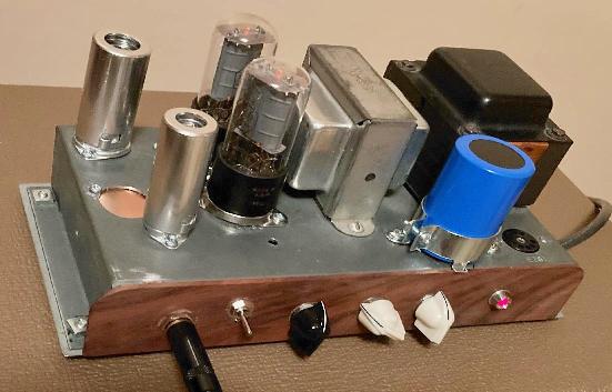
Reader William Bock has built a variation of the Spartacus amp shown above using vintage RCA 6V6 power tubes, a 6AV6 first stage and a 12AU7 for the remaining stages. The 6V6 cathode resistor has been changed to 110 ohms. The controls and guitar input were mounted on the opposite side of the chassis from the original build. The gain potentiometer was moved to the rear panel. Also note the top-mounted filter capacitor, which frees up some space under the chassis. You can see and hear two versions of this amp in action in this YouTube Video.
If you like the Spartacus amp, you may want to take a look at my Howler Monkey amp, it uses readily available 6AQ5 output tubes and transformers that can be purchased new. The Howler Monkey features a current-miror long tailed pair phase inverter circuit that provides equal gain and equal idle currents to the two PI triodes. The Spartacus Max amp is another related guitar amp project that uses a Hammond AO-35 chassis and 6L6 output tubes.
Back to FC's Music Circuits page.