(C) 2013 G. Forrest Cook
This circuit can be added to a variety of vacuum tube devices to automatically delay the application of the high voltage supply until after the tube filaments have warmed up. Vacuum tubes can be damaged or have their lifetimes shortened if high voltage is applied to the tube while the filament and cathode are warming up.
The B+ delay is a good fit for devices which use efficient solid state rectifiers. Older tube equipment used slow-warming rectifier tubes or time delay relays to perform this job. Rectifiers and time delay relays generate heat and consume a lot of power. The contacts on time delay relays will eventually burn out.
The circuit can be added to a variety of tube circuits including amplifiers, radio transmitters and radio receivers. The circuit is not suitable for devices with line-powered filament strings since it derives its operating power from the existing 6.3VAC filament transformer. The B+ delay has been tested out on my Hammonator 2RVT and Spartacus tube amps with success.
This circuit is installed in devices with high internal AC and DC voltages. The project should only be taken on by someone who has experience working with high voltage circuitry. The power cord should always be removed when working on the device. It is advisable to short out the B+ line before working on the device to discharge the power supply capacitors. Don't forget to remove the shorting jumper before applying power.
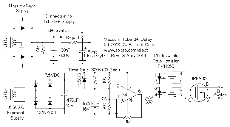
The circuit can be split into two parts, the delay timer and the optically-isolated high voltage switch. The timer gets its 7.5V DC operating power from a full-wave bridge rectifier and electrolytic capacitor powered by the tube amp's filament transformer. There are several common ways to ground a filament circuit including grounding one side, using a resistor from each filament line to ground and grounding a center tap on the transformer filament winding. The output of the 7.5V DC supply used in this circuit should be left floating (non-grounded) so that it does not interfere with the existing filament circuitry.
The timer involves a standard op-amp comparator circuit with a 1M hysteresis resistor that produces a glitch-free switching waveform. The comparator output is low-active to prevent a brief activation of the output when the circuit is powered-up. The comparator reference input (pin 3) is set to 5V by the 20K and 10K resistors. This is 2/3 of the VCC, which extends the delay compared to a typical 1/2 VCC comparator threshold.
The time delay is set by the 100uF capacitor, the 300K pull-up resistor and the internal bias components of the op-amp. These create a delay of about 35 seconds, more resistance will create a longer delay. When pin 3 reaches the 2/3 VCC point (5V), the output of the op-amp drops to the low state, turning on the two LEDs inside of the PVI1050 opto-isolator. When the power is switched off, the 1N5818 diode quickly discharges the timing capacitor to insure a full delay time when power is switched back on.
The opto-isolator is an International Rectifier photovoltaic output device that is specifically designed to drive power MOSFET transistors. It contains two sections, each includes an LED that shines on a tiny photovoltaic (solar) cell array. The two PVI1050 solar cell arrays are wired in series to produce around 10V of drive for switching on the IRF830 MOSFET. The PVI1050 provides input to output isolation of up to 2500V. The only drawback of the PVI1050 is its price, in 2018 they are selling for around $10.00 at Mouser.com. Avago makes a similar part, the ASSR-V621-002E which is available for around $4.15.
The IRF830 MOSFET is rated to switch a maximum of 500VDC with a maximum current of 4.5A. It should be wired into the tube device's B+ supply between the rectifier and the supply's first electrolytic filter capacitor. Other MOSFET transistors should also work in place of the IRF830 for controlling higher voltages. The BUZ77A is rated at 600V/2.7A and the BUZ78 is rated at 800V/1.5A.
The 100nF, 600V capacitor should be added to the rectifier output if it is not already there. The capacitor produces a ripple-free DC voltage, this prevents the IRF830 from conducting before the gate is switched on. The 100nF capacitor also attenuates transient voltage spikes that can pass through the power transformer and damage the MOSFET. The 10M resistor discharges the 100nF capacitor when the power is shut off.
The resistor labeled R-pad limits the inrush current to the first electrolytic capacitor to below the maximum of 4.5A that the IRF830 MOSFET can handle. It can also "soften" the B+ power to better simulate a tube rectifier. A typical value for R-pad will be in the range of 10 to 200 ohms at 1 to 10W, this will vary for different circuits. To calculate the value of R-pad, divide the unloaded B+ voltage by 4.5A to get the minimu resistance in ohms. For example, with a 450V unloaded B+ feeding into a discharged (0V) electrolytic, a 100 ohm resistor will limit the current to 4.5A.
The power rating of R-pad is based on the max B+ current of the powered device. For the same 450V device that uses 100mA max current, watts = I squared * R, so (0.1A * 0.1A) / 100 ohms = 1 Watt (or greater).
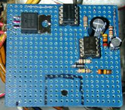
The circuit was built on a piece of perforated circuit board using point-to-point wiring. In the board shown in the above photo, the low voltage bridge rectifier was already built into the amp where the board was installed. 8 pin IC sockets were used for the 741 op-amp and the PVI1050 opto-isolator. All of the wiring that contains high voltage was isolated to one side of the circuit board and kept far from the board mounting holes and low voltage wiring. A piece of insulating plastic was mounted on top of the board to prevent any accidental contact with the board's wiring.
The 6.3VAC power to the delay circuit can be connected to the filament supply on the main power transformer, be sure not to ground any of the delay circuitry, it must be left floating.
Operation of this circuit is fully automatic and totaly transparent. Just turn on the device that it is connected to and wait. The filaments will light up, the tubes will warm up, and after the specified delay time, the B+ power will turn on and the device will be ready to use. When you are done using the device, just turn it off. If you want to include a manual standby switch, just it in series with the B+ switch connections. The switch should be rated to handle high voltage.
Back to FC's Music Circuits page.