(C) 2007, G. Forrest Cook
|
|
|
I was researching the web for electric guitar distortion effects when I came across some interesting articles on vacuum tube preamps by John Simonton on the PAiA.com site. Simonton discusses the advantages of vacuum tube preamps and running tubes in a "starved" mode for intentional distortion. Paia sells a device called the Stack-In-A-Box (see schematic) that was designed by Craig Anderton and John Simonton. The Stack-In-A-Box is designed to sound like a distorting tube power amplifier. I was intrigued by the idea of a genuine tube distortion sound and decided to use the heart of the Anderton/Simonton tube circuit as the basis for this guitar distortion pedal project.
Normally, a 12AX7 tube is run with 100-200V on the tubes plate terminals for clean amplification, lowering the plate voltage to 30V starves the tube of the regular flow of electrons and causes the tube to readily distort. Tube distortion produces pleasant sounding even harmonics, contrast that with the scratchy odd-harmonic distortion (often called crunch) that comes from transistor/diode distortion circuits. Tube distortion tends to make more of a howling electronic sound that is commonly heard in late 1960s / early 1970s rock-n-roll recordings. A good example of the tube distortion sound is Eric Clapton with Cream playing "Sunshine of Your Love". Producing tube distortion in a starved tube circuit instead of an overdriven tube guitar amp has the advantage of making good tone at much lower volume levels.
A transistor-based preamp stage was chosen so that a high voltage power supply would not be required. This makes the circuit much easier to build into a pedal format. However, this choice comes with a sacrifice in usability. The transistor's input gain must be precisely set for a good sound. An all-tube signal path would be preferable, a standard 12AX7 Fender-style tube preamp stage would make a good substitute. A common 12AV6 tube would also be a good choice for this stage since it is essentially 1/2 of a 12AX7, ignoring the extra diode connections. With a tube front-end, the clipping indicator circuitry could also be eliminated.
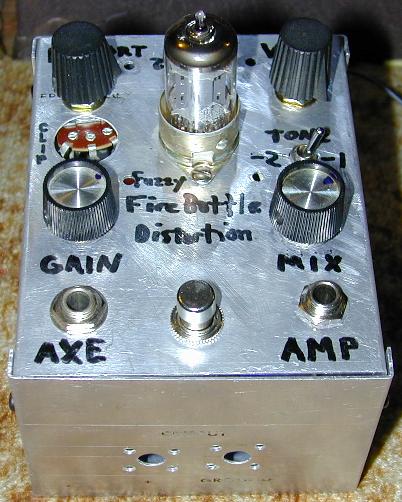
This pedal is ideal for those who like to tweak a lot of knobs. It has an input gain control, individual tube section drive controls, a clean/distort mix control, a high cut switch and an output level control. A wide variety of distortion sounds can be created by adjusting the controls. The circuit has produced excellent sounds with both Fender single-coil and Gibson humbucker pickup guitars. Unlike many distortion pedals, the Fuzzy Firebottle can mix the clean signal with the distortion signal, this produces a much fatter sound with more dynamic range and tonal variety.
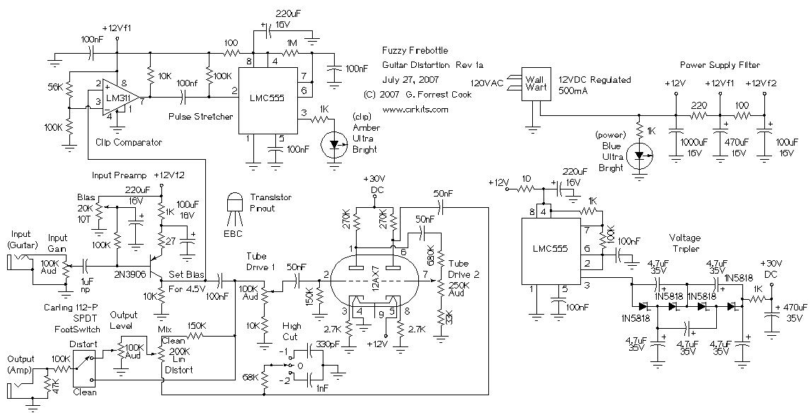
Power is supplied to the device from a 12VDC wall-wart transformer supply. Be sure that the wall-wart really produces 12VDC, many of these devices only produce their rated voltage at a given load current. A LM7812 voltage regulator (with a heat sink) may be used between a 14-18VDC unregulated supply and the distortion circuit. The +12VDC supply is initially filtered with a 1000uF capacitor, it is further filtered to the +12Vf1 and +12Vf2 supplies through two more R/C lowpass sections.
The +30VDC tube plate supply voltage is produced by an LMC555 CMOS timer chip set to generate square waves. The square waves are fed to a voltage tripler circuit which produces around 30VDC. The tripler uses 1N5818 Schottky diodes instead of regular silicon diodes to produce the full 30V. The +30V supply is filtered through the 1K and 470uF RC lowpass filter before being sent to the 12AX7 plate circuits (B+). The tube filament supply is provided directly from the +12VDC supply line.
The guitar audio signal is fed to the 2N3906 amplifier stage via a 100K input gain potentiometer. The 2N3906 bias is set to a fixed (class A) level by the 20K trimmer potentiometer. The 27 ohm emitter resistor provides negative feedback to limit the maximum gain for the 2N3906 amplifier stage. The output of the 2N3906 amplifier produces the clean signal for the mixer and the input drive to the first of the 12AX7 triode sections.
The clean signal is sent to the LM311 + input in the clipping circuit. The LM311 - input is set to a fixed 6.9VDC level. When the 2N3906 emitter signal goes above 6.9VDC with large input signals, the LM311 output signal switches from low to high. This is fed through the 100nF capacitor to the input of the LMC555 pulse stretcher circuit (one shot). On the return from high to low, the pulse stretcher triggers and the the amber LED blinks on for a few tens of milliseconds to indicate clipping.
The clean audio signal is sent to the grid of the first 12AX7 section through the 100K drive control. If the drive control is set high, the signal on the first 12AX7 plate is distorted. The plate signal from the first 12AX7 section is fed to the second drive control via a 50nF DC blocking capacitor. The signal on the second 12AX7 plate is even more distorted. The distorted signal from the second 12AX7 plate is sent through a 50nF DC blocking capacitor and fed to the Mix control.
The High Cut switch optionally puts a 68K/330pF or 68K/1nF RC filter to reduce the high frequency harmonics. The center tap of the Mix control contains a mix of the clean and distorted signals. This is sent to the Output Level control and switched to the Output jack via the foot switch and through the 100K/47K attenuator.
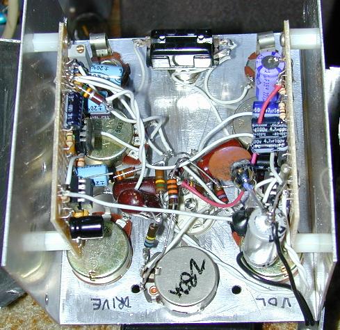
The circuit was built in a 3"x4"x5" aluminum box (see photos above). Two universal breadboard printed circuit boards were used for the solid state sections, one for the input amp and clip indicator circuitry and the other for the 30VDC power supply. The vacuum tube socket was mounted in the center of the box and the tube circuitry and controls were mounted on the top of the box. The tube circuitry was wired with a point-to-point method and short wires were used to reduce circuit crosstalk. All of the ground connections tie to a single point near one end of the tube socket to reduce ground loop hum.
The 30VDC power supply board's oscillator circuit produces a tone that can be picked up by the sensitive preamplifer input. The board should be located as far away from the preamp circuitry as possible. If the tone is still heard, it can be supressed by placing a grounded metal plate between the supply board and the preamp.
The blue power LED and amber clip LEDs were mounted to shine through the many holes in the used aluminum box. This gives a nice blue glow effect. You may want to mount the LEDs on the front panel.
Power the circuit up and verify that the +12V line and +30V line have the correct voltages. Connect a digital voltmeter between ground and the collector of the 2N3906 input transistor. Adjust the 20K bias trimmer so that the collector voltage is around 4.5VDC. This adjustment can be further tuned (by ear) for maximum volume and minimum distortion when the footswitch is set to the clean setting. There is a "sweet spot" for the bias adjustment, the volume will fall off as the bias is adjusted above and below this spot.
Connect a guitar to the circuit's input jack and a jumper cable between the output jack and the external amplifier. Plug the wall-wart supply in. Set the guitar amp's input volume to a fairly low level. Turn the guitar volume control to a fairly high setting and play some loud chords. Adjust the input gain until the yellow clip LED occasionally blinks. The blinking clip LED indicates undesirable distortion on the clean signal. The input gain control may need adjusting if you modify the guitar controls.
Set the Tube Drive 1 and Tube Drive 2 controls to the middle of their range. Set the Mix control to the middle. Step on the footswitch, adjust the Output Level control so that the distortion setting is as loud as the clean setting. When the footswitch is set to distortion, you should hear some nice fuzz sounds while the guitar is played. Adjust the tube drives up or down for the desired distortion sound, the Output Level control may need adjustment as the distortion levels are changed.
The Mix control can be moved between Clean and Distort for the desired signal mix. For a traditional fuzz sound, the control should be set to the full distortion setting. The High Cut switch can be adjusted to lower the high frequency harmonics on the distortion channel. A wide range of distortion sounds, from barely noticeable to highly distorted, can be produced with this box. Some interesting sounds can be found by moving the Tube Drive 1 control up and the Tube Drive 2 control down, or vice-versa.
For a better sounding second-generation tube distortion project, see the all-tube FuzzniKator Tube Distortion/Preamp.
Back to FC's Music Circuits page.