(C) 2008 G. Forrest Cook
In the world of high-tech electronics, vacuum tubes are considered obsolete. One of the last holdouts, the cathode ray tube (CRT), has been replaced by the LCD and other new display technologies. Despite this trend, vacuum tube circuits have seen a big revival in the fields of guitar and hi-fi amplifiers. Vacuum tubes and related parts have again become more available as numerous companies have tapped into this re-emerging market.
The reason for the popularity of tubes in guitar amps involves the nice tones that are produced when tubes are driven to the point of distortion. For some background on this, follow some of the links on The Strat Monger. There are numerous solid-state "modeling amps" that try to simulate vacuum tube amps with digital signal processing (DSP) techniques, but in the end, that method is never more than a simulation. It just ain't the same as the real thing (with a real spring).
One can spend a large amount of money and time building a tube amp from scratch. Hammond organ amplifiers chassis are often available on the surplus market for a reasonable price, they make a good starting point for a guitar amp. The difficult job of cutting chassis holes for the tubes and transformers is already done, one just needs to drill a few small holes for the potentiometers and jacks. This project started with a model AO-14-1B amplifier chassis from a Hammond M2 organ.
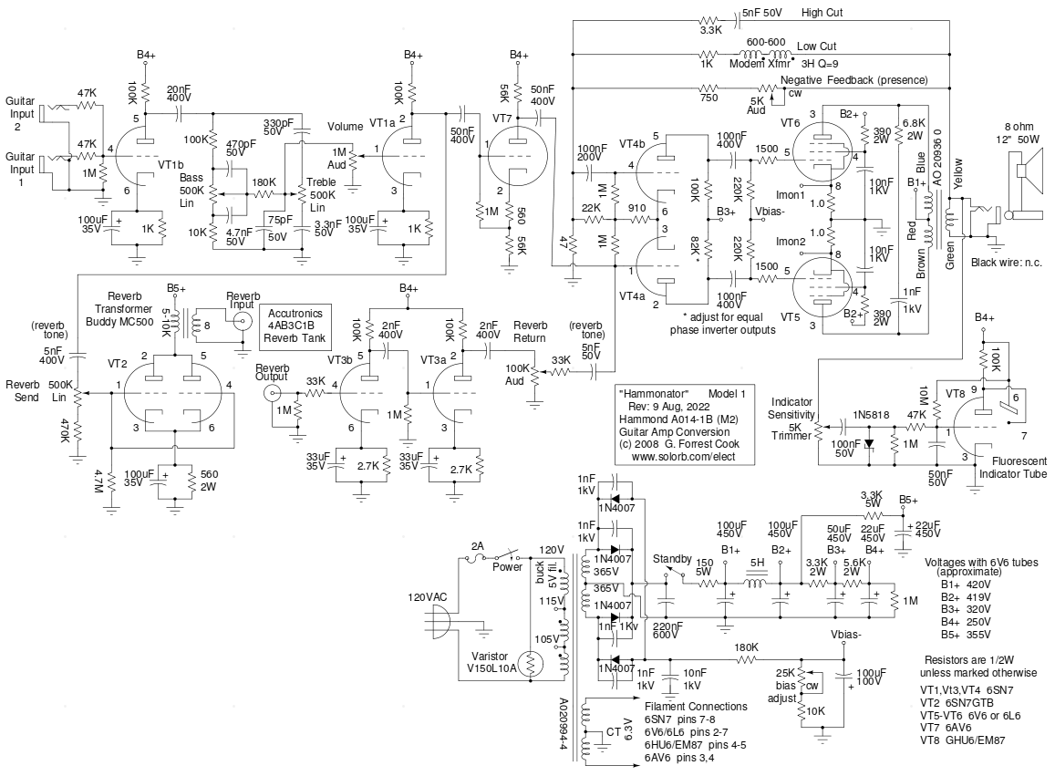
The output stage of this amplifier resembles a fusion between a Fender Princeton Reverb, Fender Vibroverb with some ham radio transmitter tricks added for good measure. With 6V6 or 6L6 output tubes running at a 420V plate voltage, the Hammonator puts out approximately 18 watts of audio power. The 17" reverb tank provides a deep echoey sound. The "simpler is better" philosophy was used in the design, multiple inputs with their own preamp stages were intentionally avoided to reduce hiss. The amp is plenty loud, and the sound quality is excellent. The Hammonator amp has worked well driving both 12" and 15" guitar speakers.
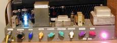
The Hammonator Model 1 amps were used as the starting point for the later Hammonator Model 2RVT amps (see photo below). The model 2RVT adds pitch-shifting vibrato and tremolo. Builders may want to start with the Model 1 circuit then add the Model 2RVT Vibrato/Tremolo circuitry and its other changes at a later date. The Model 1 circuit has been modified from the original design to include some of the tweaks and changes made in the Model 2RVT circuit.
There are a few unique features in this amp, and some slight deviations from the aforementioned simplicity goal. An optional fluorescent 6HU6/EM87 "magic eye" indicator tube is used as an output level meter, it is fun to watch while playing and makes great eye candy for the amp. The 6HU6/EM87 uses a peak reading circuit that was inspired by a design that was published on the web by Jukka Tolonen, I modified the circuit to produce a wider indicator range.
There is a reverb send control (Dwell) that can be used to expand the variety of reverb sounds. Most Fender amps send only a full-strength signal to the reverb spring. By turning the reverb send control down and the reverb return control up, a less "clangy" and more "spacey" reverb sound results.
The Hammonator also features a negative feedback control. With the feedback control turned all the way to the left (max negative feedback), the amp compresses the signal and the waveform peaks are reduced. With the feedback control turned all the way to the right, the sound is louder and less compressed, it approaches the sound of the popular Fender model 5E3 Tweed Deluxe amps. Other amp designs label the feedback control as "Clarity", "Gain" or "Presence".
This amp uses four octal-base 6SN7 dual triode tubes for most of the low level signal amplification instead of the more common 12AX7 or 12AU7 tubes. This was done because the chassis was already set up for the octal sockets. Boutique amp enthusiasts will probably like this feature since the 6SN7 tubes are an older design and may have more of a vintage amp sound. New 6SN7 tubes are now available and there are many used 6SN7 tubes on the market. The 6SN7 tube is renowned for its highly linear response.
This amp has been "tuned" for good sound, the bias settings of all of the tube stages were tweaked while a guitar was plugged in. This process was used to optimize the musical qualities of the amp. Not all vintage 6SN7 tubes are the same, quieter Sylvania tubes were used for VT1 and VT3 to reduce the hiss on the critical input stages. Noisier RCA and GE tubes were used elsewhere. Tube noise levels are not necessarily related to the brand, this was just what I noticed from my small collection of tubes. You can test for noisy 6SN7 tubes by putting them in the VT1 socket, listen for a change in the hiss level and tap on the tube to check for microphonics.
The reverb driver tube, VT2, is run at a fairly high bias level and it gets warmer than the other 6SN7 tubes in this amp. 6SN7GTA and 6SN7GTB tubes have higher plate dissipation ratings than regular 6SN7 tubes and would be a good choice for VT2.
It is possible to change VT1, the first preamplifier and tone recovery tube, from a lower gain 6SN7 dual triode to a higher gain 6SL7 dual triode. The cathode bias resistors will need to be changed to higher values. This is a comparable to swapping 12AU7, 12AT7, 12AY7 and 12AX7 tubes in more modern amps. The tubes share the same pinout but have different amplification factors and bias currents.
The newer and more common AO-29 (M3 organ) chassis would also make a good chassis for a guitar amp conversion. The three 9 pin tube sockets could be used for 12AX7 or 12AU7 dual triode tubes and the five 7 pin tube sockets could be filled with common 6AV6 tubes (similar to a single 12AX7 triode), 6C4 tubes (similar to a single 12AU7 triode) or 6S4 tubes (similar to a single 6SN7 triode). A similar circuit layout could be used on the AO-29 chassis but the cathode bias resistor values on the 7 and 9 pin preamp triodes would need to be changed from the values used on the 6SN7 tubes. The AO-29 power and output transformers are very similar to those used in the AO-14 chassis.
This is a fairly advanced-level project. It takes a lot of technician skills to deconstruct and reconstruct the amplifier circuitry. Also, there are plenty of lethal high voltages inside of this amp including 120 VAC and 420 VDC. The project should only be taken on by someone who has experience working with high voltage circuitry. The power plug should always be disconnected when working on the amp, the circuitry is designed to discharge the capacitors when power is removed, but it's always a good idea to short out the electrolytic capacitors before working on the amp. Be sure to remove the capacitor short before applying power or you may destroy the power transformer.
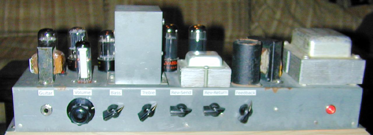
Power Input - grounded 120VAC
Guitar Input - High Impedance
Reverb Send
Reverb Return
Speaker Output - 8 ohms
On/Off (on the back)
Input Volume
Bass
Treble
Reverb Send (Dwell)
Reverb Return
Feedback (Gain)
The AC power input circuitry was modified from the original Hammond circuit. The power transformer is old enough that it was designed to run on 110V-117V mains instead of the 120V-125V mains found today. Running the stock amp on 120V produces higher filament and B+ voltages, the higher filament voltages will shorten the life of the tubes.
In this amp, the high line voltage problem was fixed by putting the 5V rectifier filament winding in series with the power transformer's primary winding. The 5V winding's phasing must be set to buck the input voltage. The easy way to test this is to try both orientations and monitor the 6.3V filament winding, use the phasing that produces the lower filament voltage. When all of the tubes are installed, the filament voltage should be very close to 6.3V.
A grounded AC cord was installed in the amplifier, this is critical for safety. A 2 amp fuse and switch were installed to provide a standard fused disconnect. A varistor was placed on the power transformer's primary winding to protect against line voltage transients, those can get multiplied on the high voltage output winding and cause damage to downstream parts.
The power transformer's high voltage winding is sent to a center-tapped full wave rectifier consisting of two 1N4007 diodes. The high voltage DC is dropped through a typical chain of resistors and capacitors to produce the voltages used in the amp. The first resistor (150 ohms/2 Watt) is used to set the initial B1+ voltage that drives the power output tubes.
There is a lot of misinformation on the net about tube rectifiers vs solid-state rectifiers and the effect on amp sound. This derives from the more efficient nature of solid-state diodes and the resulting higher voltage when a direct substitution is done. Putting a resistor after the diodes drops the B+ voltage to a level that is closer to that achieved with a 5U4 rectifier and also "softens" the amp's transient response, just like a rectifier tube. The solid-state diodes have the much better power efficiency since they don't require a high current filament. The power transformer will run much cooler using solid-state diodes. The 1nF/1KV capacitors across the diodes protect against high voltage transients and eliminate RF rectification issues.
The 5H inductor choke is used to reduce hum in the preamp stages, the value is not especially critical. The 220nF capacitor in the high voltage power supply removes power line transients from the power transformer's secondary winding. If you don't have any 220nF caps on hand, a 100nF part will work.
The Vbias- negative voltage is derived from a full-wave rectifier and an adjustable resistive ladder. The 10nF capacitor filters power line noise from the power transformer secondary winding and the 100uF capacitor removes AC ripple from the bias line. The 25K rear-mounted bias control pot can be adjusted to set the bias levels on the two power output tubes. Bias voltages that are suitable for 6V6, 5881 and 6L6 tubes can be produced. The bias currents of the individual tubes can be measured on the Imon1 and Imon2 terminals which float both cathodes above ground with one ohm resistors. Using ohms law, 25mA of current through a 1 ohm resistor will yield 25mV (0.025V) across the resistor. The Imon signals are brought out to the terminal strip on the back of the amp for easy access.
The guitar input stage, VT1b, is a standard class-A triode amplifier. The 1K cathode resistor was chosen to bias this most important amplifier stage into the "sweet spot". Note that the photo on the top of this page only shows one 1/4" input jack but the schematic shows two jacks, the second input was added at a later date.
The tone controls use the Baxandall tone stack configuration. This circuit has a much more distinct boost and cut operation when compared to many of the traditional Fender circuits. A guitar player friend had the amusing suggestion that the "Bass" and "Treble" labels should be changed to "Balls" and "Grit". The 75pF capacitor across the volume control produces high-cut action at frequencies above the hearing range which can pass through the tone stack. The tone stack recovery stage, VT1a, is another class-A triode amplifier. Again, the 1K bias resistor was chosen for the best sound.
The reverb send amp, VT2, gets its input from the tone control recovery amplifier VT1a. The 500K linear pot is used to adjust the reverb-send level from partial to full. An audo-taper pot was tried here, the linear pot had a better response. Both halves of VT2 are run in parallel for more reverb drive power. The 560 ohm VT2 cathode bias resistor was chosen for a high drive level. VT2 runs at near maximum power, with a bit of blue glow visible in the dark. A standard Fender "Twin Reverb" replacement reverb transformer can be used to drive the reverb, although that part may not drive the reverb to its full level. I used a larger Buddy MC500 transformer from my junk box. A P-T291 universal output transformer would be a good choice since it can be wired for different input impedances between 4K and 9K for the optimum reverb drive level.
The reverb return signal goes to two class-A triode stages formed by VT3b and VT3a. The reverb return level is set with the 100K audio pot and mixed into the phase splitter stage, VT4, through a 5nF capacitor. The clean (non-reverb) signal is amplified by VT7, a 6AV6 triode wired as a floating cathode-biased stage. The 6AV6 isolates the reverb send and receive signals to prevent feedback. The 6AV6 is wired in a floating cathode configuration so that it can easily be converted to the vibrato/tremolo circuit that is used in the second-generation Hammonator 2RVT design.
The balanced phase splitter circuit is formed by VT4a and VT4b. This stage combined with the power tube stage is fairly similar to the Fender Vibroverb circuit. The two opposite-phase drive signals are sent to the control grids of the 6V6 power output tubes. An RF power amp trick is used here to reduce potential radio frequency oscillation issues, 10nF capacitors bypass the 6V6 screen grids to ground. These caps should not be confused with the unpopular tone-deadening control grid caps that were added to Post-CBS Fender Twin Reverb amps.
An unusual triple feedback path is used between the output transformer and the input of the phase splitter. The jury is still out on whether this is a better design than a typical loop that has only a high-cut function or a high cut and presence control. The low-cut and high-cut loops reduce the subsonic and ultrasonic gain, eliminating low frequency oscillations and inaudible high frequency parasitics. While experimenting with the circuit, some nearly dead 6V6 power tubes were used and the tubes tended to generate RF oscillations when biased to a useful setting. This feedback loop fixed the oscillation problem and improved the sound, RF superimposed on audio does not sound good unwanted low frequencies waste a lot of the available audio power.
A fairly heavy modem isolation transformer from a 300 baud modem was wired in series to make the low-cut inductor. When the amp is driving a speaker, there can be large resonances in the low bass part of the audio spectrum. A 12" speaker in an open-backed cabinet showd a natural resonance of around 70 Hz. Audio at the speaker resonance frequency is amplified to about twice the level as other frequencies, resulting in an exaggerated bass response and distortion. The low-cut part of the feedback circuit eliminates this speaker resonance effect.
The 6HU6/EM87 indicator tube circuit gets its control signal from the speaker side of the output transformer. The signal is rectified by the 1N5818 diode, low-passed by the 47K resistor and 50nF capacitor then sent to the tube's control grid. The 10M bias resistor causes the tube's display to open all the way when the volume is low. To adjust the 5K sensitivity trimmer, feed a 1Khz sine wave into the amp's input and connect an oscilloscope across the speaker. Turn the volume up until the waveform just starts to distort, and adjust the trimmer so that the indicator tube pattern just closes.
The bias is set by putting a DC volt meter between the Imon1 terminal and ground. The Imon2 terminal can be checked to see if the power tubes are well matched. Both Imon1 and Imon2 should have similar voltages. With some patience, the Hammonator can be used to sort through a group of tubes to find matched pairs. If you a little want a bit more than 18 Watts of output power and a cleaner sound, it is possible to replace the 6V6 tubes with 6L6 tubes and adjust the bias control for a higher bias current.
The 6V6 output tubes work best with a bias of around 0.02-0.03V (20-30 mA) and 6L6 or 5881 tubes work well in the range of 0.030-0.05V (30-50 mA). Tube bias setting is a trade-off between loudness and tube life. Generally, the bias should be set so that the tubes don't become too warm when there is no signal going through them. Your author has had good luck with the JJ brand 6V6S spiral filament tubes running at a bias of 25mA. One of these amps has been set up with a pair of 1950s vintage Tung Sol 5881 tubes (similar to a 6L6) biased at 30mA and it sounds excellent.
Here is a photo of the wiring side of the second build of the Hammonator 2RVT amp. The Hammonator 2RVT is essentially the Hammonator 1 circuit with the additional vibrato/tremolo circuit, LFO board and associated controls. Note the modem transformer located behind the blue and yellow knobs.
The stock Hammond amp chassis that was used for the first build of this project was dirty, rusty and filled with mostly useless parts. After removing many of the original parts, a wire brush was used to scrape off the rust and dirt. Leave the original filament wiring from the power transformer to the 6V6 tubes intact. You will need to move one of the filament wires the tube sockets used for the 6SN7 tubes. The power transformer's high voltage leads can be left connected to the unused 5U4 socket, the 1N4007 rectifier diodes can be wired across the pins of the 5U4 socket.
The output transformer's primary wiring should be left as-is. The ground wires that connect all of the tube sockets should be left intact. Just about everything else can be clipped off, leave all of the transformer wires as long as possible. There were two plug-boards in the center of the amp. All of the wires between the plug-boards and the tube sockets were clipped at the tube sockets and the plug-boards were removed. The wires to the screw terminals were also clipped off. Some of the plug-board capacitors were scavanged for use elsewhere in the amp. Used capacitors should always be checked for proper value and good Q factor using a capacitor checker.
A new 3-wire power cord and a power switch were installed in the small metal wiring box that is located behind the power transformer. Two of the downward-facing holes in the wiring box were expanded to fit the power cord's strain relief and the switch. A plastic "pigtail" type of fuse holder was also installed in the box. The power cable's green ground wire was connected to the chassis with a solder lug.
The two tall electrolytic capacitors were removed from the chassis. The silver capacitor's hole was filed out and drilled to fit the 9 pin 6HU6/EM87 indicator tube socket. An aluminum plate was installed in the black capacitor's hole (the photo above was taken before this was done). The original volume control capacitor tower was emptied out and the space was used as a "doghouse" for most of the electrolytic capacitors. The caps were secured to the tower's bakelite spacers with panduit ties. The tower allows the amp to sit upside down without resting on the tubes, this is very useful when working on the amp.
A number of multi-point solder terminals were added to the middle of the chassis. All of the tube socket terminals were cleaned with a "Soldapullt" tool and the remaining wire bits were removed with a dental pick and wire clippers. This step takes a long time and may be eliminated if you feel lazy, you just have to work around the old wires. If your amp has any broken pins on the octal tube sockets, it is possible to remove some of the unused pins on the 5U4 socket and use those as replacements. Holes were drilled for the various input/output jacks, the solder terminals, the potentiometers, the reverb transformer and the filter choke. Use a drill press and start with a punch and a small pilot drill before making the larger holes. Sharp drills and cutting oil are essential for making good holes. Be sure to prevent the drill from "running away" and chewing up a tube socket when a new hole is nearly through.
All of the various parts were installed between the tube sockets and the solder terminals. All new resistors and electrolytic capacitors were used, old resistors tend to go up in value and may also become noisy. Some of the old signal capacitors were sticky with wax and were discarded. All newly added ground connections should go to the closest tube socket ground lug or to the wires that connect between the socket grounds. Unlike more modern tube amps that use a star grounding system, the Hammond chassis has a point-to-point ground between the tube sockets. The ground wire between the old 5U4 and 6V6 (VT6) tubes was chosen as the main power supply ground, this point is also used for the electrolytic capacitor grounds.
Plug the amp into a guitar speaker. Plug an electric guitar into the input. Tweak the knobs for a good sound, start playing and enjoy the amazing sound. Effect pedals are not required when using this amp, although they can be fun to play with. Remember, as with all tube-amps, putting a solid-state pedal between the guitar and amp loses much of the benefit of the all-important tube preamp stage and its wide dynamic range. Your author has had very good results using the FuzzniKator tube distortion circuit in front of the Hammonator amp.
If you liked this project take a look at its evolution, the Hammonator 2RVT. The 2RVT design adds tremolo and the much coveted pitch-shifting vibrato effect (similar to Magnatone amps) which can produce an incredible moving stereo effect when paired with a second amp. This project also inspired the Lil' Tiger project, which uses the smaller Hammond AO-43 chassis as a starting point. The latest organ amp conversion project in the Hammonator series is the Hammonator 29R, which uses the Hammond AO-29-10 (M3 organ) chassis and features some really nice reverb circuitry.
See the Head-Fi.org 6SN7 Identification Guide for just about everything known to mankind about 6SN7 tubes. Wikipedia has an interesting article about the history of the 6SN7. Lastly, it should be possible to substitue other dual triodes for the 6SN7 tubes in this circuit. Medium power triodes such as the 6GC7/6FQ7 or 12BH7 should work in place of the 6SN7 without changing any bias resistors. These tubes use 9 pin miniature tube bases, so some chassis re-work would be required.
Back to FC's Music Circuits page.