(C) 2009-2023, G. Forrest Cook
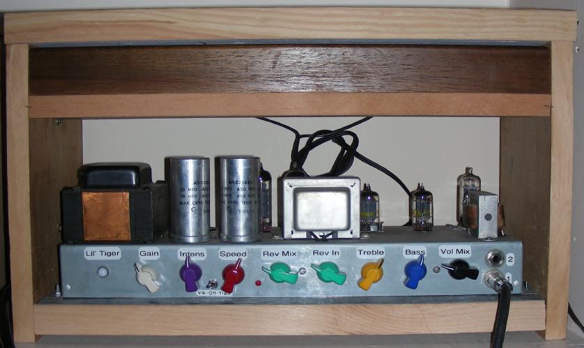
Build #2 of the Lil' Tiger amp with 6FQ7, the reverb tank is above the amp
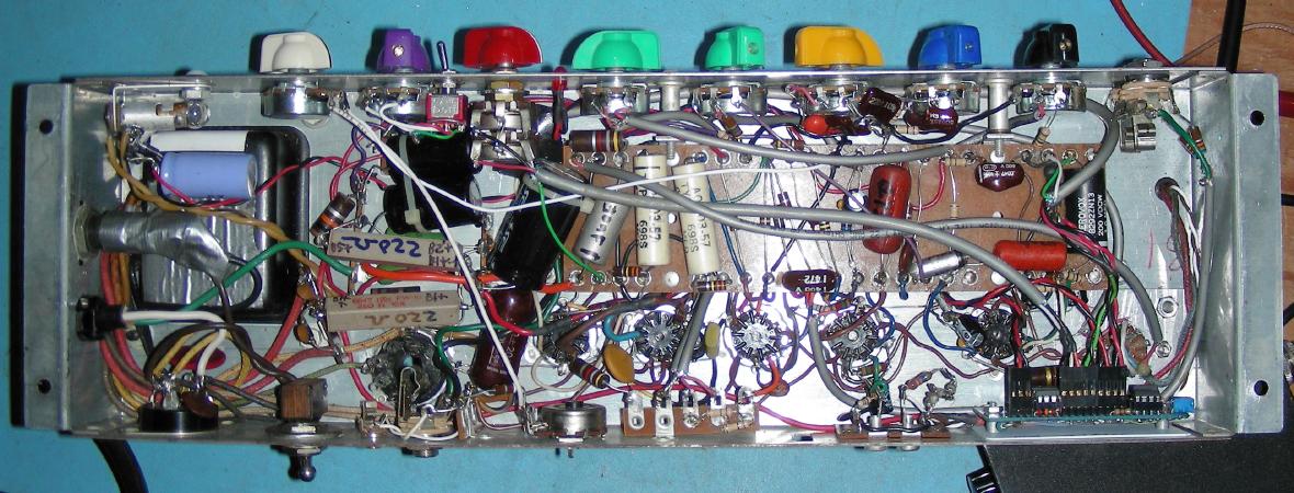
Build #2 of the Lil' Tiger amp underside, click on above photo for a larger image.
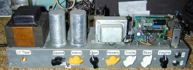
Build #1 of the Lil' Tiger amp
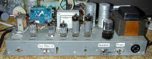
Build #1 of the Lil' Tiger amp with 6SN7, rear view
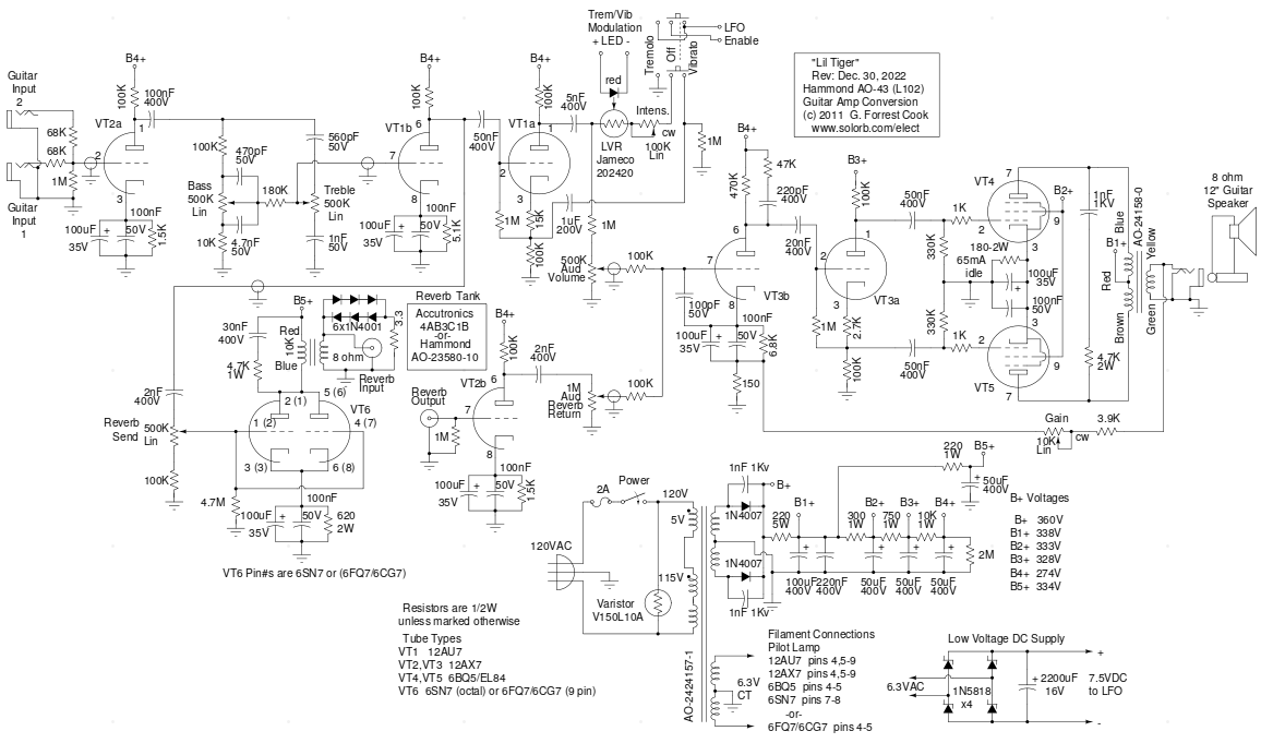
Schematic of the Lil' Tiger amp
This project follows in the footsteps of the Hammonator and Hammonator 2RVT organ to guitar amplifier conversion projects. A variety of Hammond tube amps are available on eBay for reasonable prices and they make a good platform for a guitar amplifier project. The Hammond AO-43 chassis is a prime candidate for conversion, it is large enough to build a full-featured amp with reverb, vibrato and tremolo effects, and it has a handy bare chassis side that can hold many knobs and jacks.
This amp has undergone a number of design changes since the original version (with yellow, black and white knobs) was built and published. A second copy of the amp (with multi-colored knobs) was constructed and the reverb driver tube was changed from an octal-base 6SN7 to a 9 pin 6FQ7/6CG7. The 6FQ7 tubes are of the same vintage as the other tubes in the amp and are typically less expensive than 6SN7 tubes.
The reverb driver circuitry was changed to include a Reverb Send (Dwell) control, this gives the amp a much wider variety of reverb sounds. The vibrato circuit was rebiased to produce a more intense effect. The Arduino LFO was reduced to a single board and was moved to the inside of the amp chassis. I liked the build 2 modifications enough that they were applied to the build 1 version of the amp.
The volume and reverb return controls in this amp are wired in a mixer configuration which is somewhat unusual for guitar amp designs. This makes it possible to listen to the reverb channel by itself or to have a mix with very heavy reverb. The amp can also be used in parallel with another amp as an independent reverb channel for a stereo effect. The reverb driver also includes a unique diode clipper circuit. If the reverb send control is turned up, a pleasant sounding distorted reverb sound (fuzz-verb) is produced.
The output stage of this amplifier uses 6BQ5/EL34 pentodes wired in a cathode-biased push-pull configuration, audio power output is around 15W. In the Hammonator project, almost all of the original circuitry was replaced. In this amp, most of the original power amp circuitry was re-used. All of the resistors that will be re-used should be checked to verify that they still have the correct value. Resistors that are out of tolerance should be replaced. Old carbon resistors that dissipate a lot of power tend to go up in value, they can also become noisy.
The pitch-shifting vibrato effect can be somewhat subtle when the amp is played by itself. To get the most out of the vibrato effect, a second amplifier should be plugged into Guitar Input 2 to tap into the input signal. The resulting stereo signal moves around the room in a manner that sounds a lot like a rotating Leslie speaker. Beware, once you get used to playing through a stereo setup all other amps will sound flat and boring.
One could consider this to be a left-handed amp, the signal path and knobs are mostly right to left. The tube layout on the chassis made this necessary. If the amp is mounted upside-down in a cabinet, the controls are then arranged in the more familiar left to right direction, tube retainer clips should be used in this configuration.
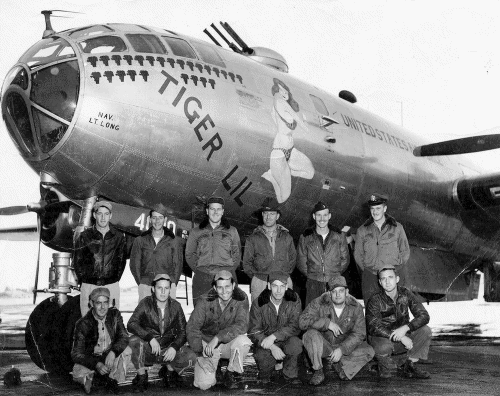
It should be noted that there's an old solid state amp design called the L'il Tiger from the December 1967 edition of Popular Electronics, the apostrophe is differently located on that amp. As Frank Zappa said: "The crux of the bis'cuit is the apostrophe". A bit of Internet searching also revealed photos of a WWII B29 bomber known as Tiger Lil, don't mess around with Tiger Lil.
This is a fairly advanced-level project. It takes advanced technician skills to deconstruct and reconstruct the amplifier circuitry. Also, there are plenty of lethal high voltages inside of this amp including 120VAC and 350VDC. The project should only be taken on by someone who has experience working with high voltage circuitry. The power cord should always be removed when working on the amp, the circuitry is designed to discharge the capacitors when power is removed, but it's always a good idea to short out the electrolytic capacitors before working on the amp.
Power Input - grounded 120VAC
Guitar Input 1 - High Impedance
Guitar Input 2 - High/Low Impedance
Reverb Send
Reverb Return
Speaker Output - 8 ohms
On/Off (on the back)
Clean/Vibrato Volume
Bass
Treble
Reverb Send Level
Reverb Return Volume
Gain (P.A. Negative Feedback Adjust)
Vibrato/Tremolo Speed
Vibrato/Off/Tremolo Select
Vibrato/Tremolo Intensity
The guitar input jacks are configured in the typical Fender-style High/Low inpedance configuration. The input options are: high(1)-or-low(2) impedance, or high(1)-and-high(2) when both jacks are used. The combined inputs are fed to a standard 12AX7 triode preamplifier (VT2a). The preamp output drives a Baxandall tone stack with bass and treble controls.
The output of the tone stack is fed to a 12AU7 triode buffer amplfier (VT1b). The output of the tone stack buffer amp feeds the 12AU7 vibrato stage (VT1a) and the 6SN7 (build #1) or the 6FQ7/6CG7 (build #2)) reverb driver (VT6).
The VT1a vibrato stage uses a 12AU7 triode wired as a floating cathode switchable phase shift (vibrato)/volume shift (tremolo) circuit. The effect is switched between tremolo, off and vibrato with a selector switch. The other part of the switch enables/disables the LFO. The programmed wafeform from the LFO drives the LED and modulates the light variable resistor. The LVR modulates the effect and the intensity control adjusts the amount of effect.
The reberb driver tube (VT6) can be either a 6SN7 octal tube or a 6FQ7/6CG7 9 pin miniature tube. The two tube types are very similar medium power dual triodes. The original AO-43 amp used a 12BH7 tube which would probably work here with appropriate pin changes, although this has not been tried. The reverb driver tube is wired with the two triode sections in parallel, this behaves like a single large triode configured as a single-ended triode (SET) power amp.
The 2nF capacitor on the input of the reverb driver acts as a high pass filter for reducing boomy bass sounds. A builder could add a switch to select different capacitor values for more reverb tone variety, values in the 1nF to 2nF range work well. The reverb send pot allows the reverb spring drive level to be adjusted. If you experience too much reverb drive at the low setting, try reducing the 100K resistor on the low end of the drive control to 33K.
The reverb driver tube feeds into the reverb transformer which lowers the impedance and drives the input side of the reverb tank. The 30nF/4.7K rc network that is across the reverb transformer's primary acts as a high cut filter and improves the reverb driver's behavior with large signals.
The six diodes and 3.3 ohm resistor across the reverb transformer's secondary act as a soft limiter that clips at around 6V P-P, this prevents large signals from slamming the reverb spring too hard and making unpleasant sounds. It also reduces the chances of burning out the reverb driver coil. The diode limiter/clipper adds another useful sound effect. If the reverb send level is turned up above about half way, a clipped drive signal is sent into the reverb spring which produces a fuzzy reverb sound. The 3.3 ohm series resistor in the diode clipper softens the clipping action for a smoother sound.
The reverb spring output feeds the reverb return amp (VT2b), a 12AX7 triode preamplifier. The 2nF capacitor in the reverb return amp's output acts as a high pass filter to reduce undesirable low frequency reverb sounds. As with the reverb input capacitor, different capacitor values can be used here for more tonal variety in the reverb channel.
The output of the vibrato/tremolo circuit and the reverb return amp are combined in a two channel volume/reverb mixer circuit. The vibrato/tremelo signal is reduced by the 1M resistor above the volume control pot, this balances the clean/vibrato level relative to the reverb signal. The mixer output signal drives the power amp circuitry.
The rest of the amplifier is close to the original circuit from the Hammond AO-43 amp. Differences include a few additional cathode capacitors and movement of the Gain control (negative feedback adjust) to the front panel. The gain control contours the amp's behavior, it adjusts the amp's gain and signal compression characteristics. The cathode resistor on the two 6BQ5 output tubes has been changed from 130 ohms to 180 ohms to set the output stage idle current to around 65mA, a 150 ohm resistor can be used here if you want to run your tubes a bit hotter. Triode VT3b boosts the mixed signal and includes an R-C snubber network on the plate and a negative feedback input from the speaker output to the cathode.
The VT3b output goes to VT3a, the floating cathode phase inverter. VT3a provides the two out-of-phase signals which drive the two 6BQ5/EL84 pentodes VT4 and VT5. The 6BQ5/EL84 tubes are wired in a standard push-pull configuration. The 4.7K/1nF low-pass RC network across the output transformer's primary is common in this vintage of Hammond power amps, it supresses high frequency parasitic oscillations (snivets) which can cause unpleasant sounds and destructive arcing in the output transformer.
The power supply uses a varistor on the transformer's primary winding to prevent power line voltage spikes from being multiplied and sent through the rectifier diodes. A Class Y power-line supression capacitor of around 10nF can be used in place of the varistor. The transformer high voltage winding drives a center-tapped full-wave rectifier consisting of two 1N4007 diodes. The high voltage DC is dropped through a totem-pole array of resistors and capacitors to produce the voltages used in the amp. It is a important to disconnect all of the original electrolytic capacitors and replace them with new parts. The two electrolytic cans can either be removed or left in place, they can be useful for protecting the vacuum tubes when the amp is turned upside down to work on.
The 220 ohm/10W resistor drops B1+ to around 338V, which is about what the tube rectifier produced. This resistor also "softens" the sound of the amp a bit, just like a tube rectifier would. By eliminating the huge tube rectifier filament, the amp becomes more power efficient and the power transformer runs much cooler. My B+ delay circuit could be added to this amplifier's power supply circuit if an automatic power supply delay is desired. The reverb driver B5+ line is tapped off with a separate RC filter near the high voltage end of the power supply totem pole.
The Arduino LFO Waveform Generator V2 is used to generate the Tremolo/Vibrato modulation waveform. The 7.5V DC Power for the LFO comes from a bridge rectifier and 2200uF/16V capacitor that is fed by the 6.3VAC filament line. 1N5818 Schottky diodes are used in the low voltage power supply instead of normal silicon diodes in order to produce a slightly higher DC voltage and give the 5 Volt regulator IC more headroom. Be sure to keep the LFO "ground" isolated from the chassis since it rides on the 60 cycle filament signal. The above photos show the original prototype of the LFO. In the second version of the amp, the LFO circuit was reduced to a single circuit board and mounted inside of the amplifier chassis.
Before building the Lil' Tiger amp, be sure to make a temporary wooden side-leg to prevent the inverted amp from resting on the fragile tubes while it is being worked on. A 5" long piece of 1"x4" (or wider) piece of wood can attached to the chassis mounting flange with a wood screw, it should be placed opposite from the power transformer and pointing to the upper side of the chassis. The inverted amp can now rest across the wooden leg and the power transformer.
Note that the photos of the first build of the amp do not show the Reverb Send control, it was added at a later date. The Reverb Send (in) control is visible on the front panel of the second build of this amp.
When building the amp, the first job is to install new 120VAC wiring. A grounded power cord should be installed and a fuse and switch should be added. The round black four pin connector on the back of the amp can be used as a terminal strip for the modified 120VAC wiring, this includes the 5V transformer winding and the varistor. An aluminum plate was cut and drilled to fit into the hole that used to house the square multi-pin connector. The power switch was installed in this plate.
When this amp was originally made, power line voltages were around 115VAC, they are now 120VAC. By switching to solid state rectifier diodes, the power transformer's 5V winding can be freed up and used as a buck winding for the transformer's primary. This makes the power transformer compatible with 120VAC and prevents the tube filaments from running at 7V, which would cause shortened tube life.
The 5V winding needs to be phased correctly when connected in series with the power transformer's primary winding. Measure the 6V filament voltage, then (carefully) try both polarities with the 5V wires, use the orientation that produces the lower voltage on the 6V transformer winding. With all of the tubes installed, the final filament voltage should now be around 6.5V.
If you decide to use a 6SN7 for the reverb driver tube, all of the wiring on the octal 5U4 rectifier tube socket should be removed. The 5U4 socket can now be used for the 6SN7 reverb driver tube. If a 6FQ7/6CG7 tube is used instead of the 6SN7, the tube's socket should be located in an aluminum plate that sits in the empty capacitor hole next to the 12AU7 tube. The location of the 6FQ7 is preferred over the 6SN7 location since the latter is close to the power transformer and can pick up hum. This is a minor issue since the reverb tank filters out most of the hum.
A three pin terminal strip was mounted under one of the power transformer's chassis screws, it holds the 1N4007 rectifier diodes. The original electrolytic capacitors in an amp this old are very likely shorted, or dried out and lower in value. Old shorted capacitors can overload and destroy the power transformer. Clip the wiring off of the old capacitor terminals, twist off the mounting terminals and remove the electrolytic capacitors. Cut a small metal plate to fit over the old capacitor holes, secure the plate to the chassis using two 6-32 machine hardware. It may useful to install some new terminal strips in this area that can support the new electrolytic capacitors.
The plug board that contains most of the parts should be relocated toward the center of the chassis to provide room for the front panel controls. The plug board's mounting screws should be replaced with longer screws and 1" spacers should be installed between the chassis and the plug board's mounting flanges.
With the exception of the filament wiring, the rest of the circuitry around VT1 and VT2 should be removed. The original VT1 and VT2 circuitry should be removed from the plugboard, the plugboard can be refilled with parts for the new circuitry. The tone stack parts should be soldered directly to the back of the tone pots. One of the leads of the original gain trimmer pot can be left in place and used as a connection point, this connects to the front panel's Gain control pot.
Coaxial wire should be used for guitar input and the audio lines that go to and from the tremolo/vibrato and tone stack circuits. Only ground one end of the coax shield to prevent ground loop hum from occurring.
Holes were drilled in the chassis for mounting the various input/output jacks and control potentiometers. Use a drill press and start with a small pilot drill before making the larger holes. Sharp drills and cutting oil are essential for making good holes. Be very careful not to drill through the metal and rip into the internal parts. Remove the choke coil and the electrolytic capacitor that is covered with black cardboard. Fashion an aluminum plate to fill the hole where the electrolytic capacitor was located. The reverb transformer can be placed in one or both of the holes where the old choke coil used to reside.
The finished amp chassis can be mounted in a wooden box as shown in the above photo. A piece of galvanized iron ducting material, or similar, should be cut to fit under the chassis there shoud be an 1/8" overlap on the front and back edges. Holes should be drilled in the bottom plate so that they line up with the four amp chassis flange holes. The edges of the iron should be filed smooth and sanded to prevent cuts. A simple wooden frame can be built out of 1"x7" shelving material and some (nominal) 2"x8" framing lumber. The boards shoud all be cut to the appropriate widths to make the bottom, reverb shelf, top, two sides and shelf front cover. The boards should all be cut to the same width using a table saw, excluding the shelf front.
Drill four clearance holes through the amp chassis flange holes and the bottom wood board. The amp chasis and bottom plate should be screwed to the bottom board using 8-32 machine screws, washers and nuts, remove the chassis before assembling the rest of the box. Through-holes and pilot holes should be drilled into the various wood pieces where they join together. Counter-sunk wood screws can be used to join the box sections together, two screws should be used for each wood joint. Screw all of the boards together, leave the top board off until the reverb and shelf front are installed.
The reverb tank is mounted inside the shelf that is above the amp chassis. To minize hum pickup in the reverb return circuit, the tank should be mounted with the connections facing to the back of the amp and the tank should be located away from the power transformer.
A metal carrying handle can be attached to the side of the box, opposite of the power transformer, be sure to use heavy-duty mounting screws or machine screws that go through the wood. It would be a good idea to install a screen across the back of the box to protect the tubes. The screen should allow air to flow by the tubes to prevent over-heating.
Many of the parts used in these amps came from your author's collection of new and used parts. If any used resistors and capacitors are used, it is important to test the parts to make sure they are within tolerance and the capacitors have low leakage. All of the electrolytic capacitors used in this project were new parts, those can be purchased from Jameco or Antique Electronic Supply.
New JJ brand 6BQ5 output tubes were used in both amps, all of the other tubes were used. All of the used tubes were tested in a GM-reading tube tester to insure that they had gains that were in-spec. It is a good idea to tap on the side of the first preamp tube VT2 to insure that it is has low microphonics.
The reverb driver transformer was a common single-ended 10K ohm to 8 ohm output transformer from your author's junk box. A suitable replacement would be a universal output transformer such as the AES P-T291 8W Output transformer. If you use this part, the primary connections should be to the brown and blue wires and the secondary connections should be to the common and tap 2 pins.
Plug the amp into a guitar speaker. Plug an electric guitar into input 1. Tweak the knobs for a good sound, play the guitar, enjoy the great tube sound. Fifteen watts may not seem like a huge amount of power, but this amp can get very LOUD. The two reverb controls and the two vibrato/tremolo controls can all be adjusted to create a very wide variety of sounds.
The Fuzznikator push-pull tube distortion circuit makes a nice companion for this amp and a counterpoise slave amp such as the Spartacus can be plugged into the Lil' Tiger's second input jack to create an incredible moving stereo sound. For even more stereo vibrato fun, a second pitch-shifting vibrato amp such as the Hammonator 2RVT can be fed in parallel. The resulting dual vibrato sound is truly dizzying.
Back to FC's Music Circuits page.