(C) 2012-2022, G. Forrest Cook
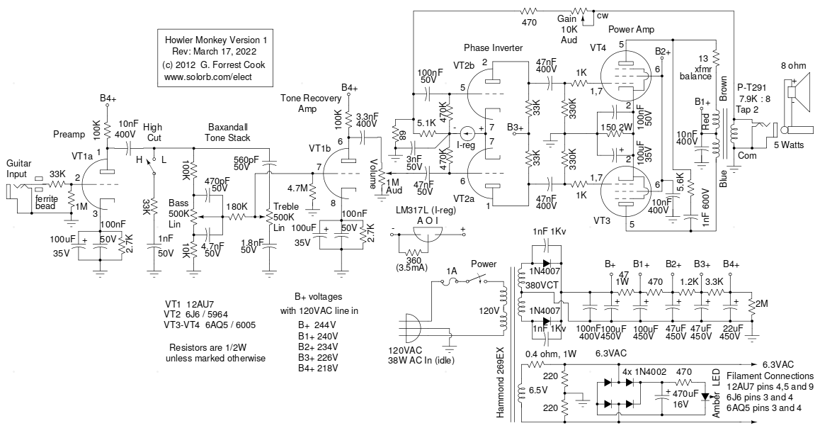
This spiffy little amplifier uses a push-pull design featuring a pair of 6AQ5 beam power tubes driven by a 6J6 dual triode phase inverter, all of which are 7 pin miniature tubes. It is the amp that I designed after my popular Squirrel Monkey one-tube amp. The only thing this amp has in common with the Squirrel Monkey is the choice of an electrical wiring box for the chassis and a monkey in the name. The 6AQ5 output tubes were commonly used for single ended audio output amplifiers in radios and televisions, they are plentiful and inexpensive on the surplus market.
The 6AQ5 output tubes are described in the RCA receiving tube manual as being lower voltage versions of the larger 6V6 beam power pentodes. The maximum undistorted power output from this amplifier is about 5 watts, which is plenty loud for a practice amp. The amp can drive an 8", 10" or 12" guitar speaker. A big advantage of the lower power 6AQ5 output tubes is their ability to reach plate starvation, with it's inherently pleasant sounding distortion, at much lower volume levels. This can be an advantage for recording, and for those who wish to preserve their hearing. There are several military versions of the 6AQ5 including the 6005, the 6669 and the 6094, the latter is a 10K-hour tube with ceramic spacers and thick glass.
The 6J6 dual triode is ideal for use as a long-tailed pair phase inverter since the two cathodes are tied together internally. The preamp and tone control recovery amps use a common 12AU7 dual triode, higher gain 12AT7 and 12AX7 tubes may be substituted for the 12AU7 if more gain is desired, see the Variations section below. If one wishes to build the amp using only 7 pin tubes, two common 6C4 triodes can be substituted for the 12AU7. Another combination of 7 pin tubes that should work nicely would be to use a higher gain 6AV6 triode for the preamp stage and a lower gain 6C4 triode for the tone recovery amp stage. 6AV6 tubes tend to be microphonic, so you may need to hand-select a quiet tube.
This is a fairly high-level project. It takes advanced technician skills to construct the amplifier circuitry. Also, there are plenty of lethal high voltages inside of this amp including 120 VAC and 250 VDC. The project should only be taken on by someone who has experience working with high voltage circuitry. The power cord should always be removed when working on the amp, the circuitry is designed to discharge the capacitors when power is removed, but it's always a good idea to short out the electrolytic capacitors before working on the amp.
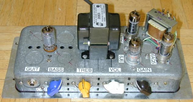
Power Input - grounded 120VAC
Guitar Input - High Impedance
Speaker Output - 8 ohms
Power On/Off
High Cut
Bass
Treble
Volume
Gain
The guitar input jack feeds into the grid of preamp VT1a, one of the 12AU7 triodes through a ferrite bead and a 33K grid stopper resistor. The ferrite bead and grid stopper filter out unwanted radio frequency interference that may get into the preamp from any nearby RF sources.
The preamp output drives a Baxandall tone stack, which feeds the second 12AU7 triode tone recovery stage. The tone recovery triode feeds the volume control pot. The high cut switch places a low pass filter into the circuit after the preamp stage to roll off the highest frequencies from the input signal.
The output from the volume control pot drives VT2a, half of the current-mirror long tailed pair phase inverter circuit. The common cathode in VT2 is pulled low through a current regulator circuit. The current regulator is simply a LM317L variable voltage regulator wired as a constant current circuit, it is set to limit the current to 3.5mA.
The current regulator allows both halves of VT2 to run at the same idle current, while maintaining equal gain from both of the VT2 triodes. A resistor is often seen in place of the current regulator in this circuit. With a resistor, one has to choose either constant gain or equal tube current, but not both at the same time. Max Robinson's article on phase inverters inspired this design, it is also has similarities to the phase inverter in the Fender twin reverb amp.
The two out-of-phase signals from the phase inverter stage drive the grids of the two 6AQ5 pentodes via two 47nF DC blocking capacitors. The 6AQ5 pentodes are cathode-biased through a 150 ohm, 2W resistor and associated bypass capacitors. The 6AQ5 pentodes are wired in a push-pull configuration and drive the output transformer, a P-T291 standard replacement type. The 1nF capacitor and 5.6K resistor across the 6AQ5 plate circuits act as a snubber which absorbs super-sonic signals instead of sending that energy to the output transformer. These signals can cause unpleasant sounding distortion and may even cause the transformer windings to arc over.
The amp features an adjustable negative feedback (Gain) control that feeds some of the speaker signal back to the input of the phase inverter. The gain control could also be called a "presence" control. The gain control adjusts the amp's compression and linearity and adds to the range of sounds that the amp can produce. When the gain control is at the maximum resistance, the amp is essentially running with no negative feedback, which should please all of the Fender 5E3 fans out there. When the gain control is at lower resistance, the amp becomes more linear and less punchy, which is great for creating a mellow Jazz guitar sound.
A few extra components in the circuit deserve explanation. The 100nF capacitors on the cathodes of VT1a, VT1b and VT3/VT4 improve the high frequency response of the various amplifier stages. The electrolytic capacitors in the various cathode circuits have a fair amount of self inductance that affects their performance at high frequencies and the parallel 100nF capacitors pass high frequencies more effectively. The 4.7M resistor on the grid of VT1b eliminates scratchy sounds from the bass control by presenting a high impedance DC connection to ground that bypasses the bass control slider contact. The 100nF capacitor across the B+ line filters out any high frequency line noise that may come through the power transformer and rectifier diodes.
The 3nF capacitor on the negative side of the current regulator prevents an oscillation that can occur in one of the phase inverter triodes. The 10nF disk capacitors on the 6AQ5 screen grids and output transformer center tap stabilize the circuits by bypassing high frequency signals to ground. The 13 ohm resistor in series with the brown output transformer wire equalizes the DC resistance of the transformer windings for optimal balance and even-harmonic rejection.
In the power supply section, the transformer high voltage winding is sent to a center tapped full wave rectifier consisting of two 1N4007 diodes. The high voltage DC is dropped through a totem-pole array of resistors and capacitors to produce the voltages used in the amp. The 6.3VAC filament supply is rectified by four 1N4002 diodes and filtered by a 470uF capacitor to produce around 7.5VDC. The DC voltage drives an amber LED through a 470 ohm current limiting resistor.
There is an 0.4 ohm resistor in series with the filament winding on the power transformer, this resistor is used to tweak the filament voltage to exactly 6.3VAC. Without the resistor, the tubes will run a bit hot and will wear out more quickly. You may want to adjust or eliminate this resistor to compensate for your average local power grid voltage. For best results, the filaments should be kept in the range of 6.1VAC to 6.5VAC. The two 220 ohm resistors across the filament winding help to reduce hum pickup from the filament wiring.
The 6AQ5 and 6J6 tubes are almost always available on eBay for reasonable prices. The knobs, power transformer and output transformer were purchased from Antique Electronic Supply. The jacks, potentiometers and resistors were purchased from Mouser and the electrolytic capacitors were purchased from Jameco. Everything else came from your author's junk box. None of the parts should be too difficult to find from the above sources.
A 70 square inch electrical switch box was used for the amp's chassis, a piece of sheet metal was cut and drilled to make the bottom plate. Inexperienced builders may want to use use a slightly larger metal box since the wiring is quite tight inside this enclosure.
Four pieces of wood were cut to form a wooden case with open front and rear sides. The amp is attached to the box and the bottom metal sheet using four machine screws. Stick-on rubber feet were applied to the corners of the bottom of the box to prevent scratching. A metal carrying handle was attached to the left side of the wooden case using wood screws.
The jacks, power switch, LED and control potentiometers were all mounted in the center of the box knockouts. The moving side of each box knockout was secured to the chassis by drilling a small hole next to the knockout and inserting a small 6-32 screw and nut. After the knockouts were secured, the holes in the center of each knockout were punched and drilled. An alternative to doing all of this work on the knockouts would be to fashion front and back plates out of aluminum or double-sided printed circuit stock. Knock out all of the plugs, screw the two plates to the chassis and drill the jack and potentiometer holes in the plates. The power cord was secured to the box with a standard romex cable clamp.
The tube sockets were all mounted inside of the knockout holes on the top of the box. The 9 pin tube required drilling two small 4-40 screw holes in the chassis. The 6AQ5 tube sockets were installed in 1/2" knockout holes by using a jeweler's rat-tail file to make semi-circular holes to accept the mounting screws. Flat washers were used on the bottom of the 7 pin 6AQ5 socket mounting holes to insure a good physical connection to the box. The 6J6 socket was installed in a small aluminum plate using two 4-40 machine screws. The aluminum plate was installed in a 3/4" knockout hole and secured with two 6-32 machine screws.
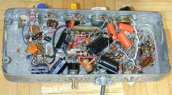
A number of three and five pin terminal strips were screwed into the bottom of the box. The internal wiring was done between the tube sockets, terminal strips, jacks and potentiometers. It is important to wire all of the filaments lines with twisted pair wiring, do this before constructing the rest of the circuitry. All of the amp's ground connections were tied together with pieces of bare #22 gauge tinned bus wire. This type of ground is not quite as good as a star-ground system, but the amp's hum level is very low.
In Rev 1 of the amp's layout, the connections from the power transformer's high voltage winding to the rectifier diodes was too close to the treble control's contacts. This caused hum to be picked up and amplified. This problem was fixed by putting a wide piece of braided copper wire between the high voltage AC signal and the tone control. The braid was covered with plastic tubing and was grounded on both sides.
If you build the amp in a larger box, it would be a good idea to move the transformer and power supply components farther away from the sensitive preamp section. An improved layout would involve placing the preamp tubes on one side, the power tubes in the middle and the power transformer, rectifiers and filter capacitors on the other side.
The preamp/tone recovery tube is specified as a 12AU7 type. The 12AU7 is a lower-gain and more linear tube than some higher gain dual triodes and it has plenty of gain for this circuit. The 12AU7 will produce a softer and warmer tone compared to higher gain tubes like the 12AX7, it will also produce less hiss. If you want to experiment with higher gain dual triodes such as a 12AT7 or 12AX7/7025, it would be a good idea to increase the value of the two 2.7K cathode resistors, 3.9K or 4.7K would be good starting values.
The P-T291 output transformer is wired to use the 8 ohm output tap. There are also taps for 4 ohms and 16 ohms available. If you want to use this amp with 4 or 16 ohm speakers, just connect the hot side of the output jack to the appropriate tap. The gain control should remain connected to the 8 ohm tap. A switch can be inserted between the output jack and the extra tap or taps if the amp is used with multiple speaker impedances.
Plug the amp into a guitar speaker. Plug an electric guitar into the input. Tweak the knobs for a good sound. Play the guitar and howl away. Enjoy the warm vacuum tube sound! The Fuzznikator push-pull tube distortion circuit makes a nice companion for this amp.

Back to FC's Music Circuits page.