(C) 2008-2022, G. Forrest Cook
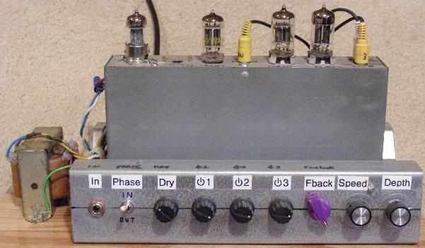
Front of the Liquidator V2.
This project involves the conversion of a Hammond AO-47 organ vibrato unit into a multi-phase phaser/chorus effects box for electric guitars and keyboards. The Liquidator name comes from the liquidy sounds that the device creates, it wiggles the audio all around. This device can be used to make an incredible stereo effect, just plug the instrument into the liquidator input and plug two amps into the Dry and Wet outputs. The FuzzniKator Tube Distortion/Preamp can be used ahead of the Liquidator to make a nice tube-based effect chain.
This project sat nearly idle since it was first built in 2008, your author finally got around to updating it in 2022 and the Version 2 circuit features a number of improvements. The main difference in the Version 2 circuit is the addition of a 6C4 inverter stage which flips the Phase 2 signal to align with phase 1 and 3, this greatly improves the sound of the chorus effect. The V4a and V4b stages were re-biased and several capacitor values were changed to lower the bass response. The original LFO was replaced with my version 2 LFO which features an improved waveform and a much wider range of LFO speeds. Finally, a dry channel output was added for stereo effects.
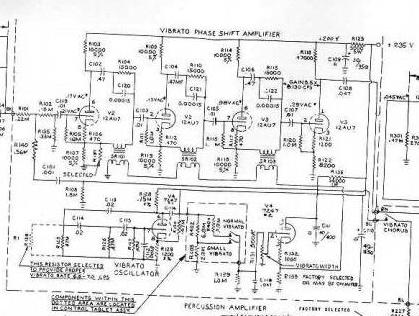
Used Hammond vibrato units can often be purchased for not much money on eBay, they provide the most important circuitry used for this device. Both the Hammond AO-47 and AO-41 vibrato units can also be used for this project, the AO-41 includes the extra 7 pin tube socket that is used in this version of the circuit. Here is the original Hammond AO-47 Schematic for reference. With its multi-phase outputs and wide-range LFO, the Liquidator allows the AO-47 to produce many more sounds compared to its original configuration.
Builders should have appropriate technical and metal working skills when attemping to re-create this project. A chassis and power supply with input and output jacks, power input, knobs and switches needs to be constructed. The AO-47 box needs many soldering modification to convert it to the phaser/chorus circuit. Additionally, an LFO circuit needs to be constructed from an Arduino microprocessor platform to make the appropriate modulation waves. Thanks to the all-tube signal path, the audio quality of this phaser is quite good when compared to solid-state phaser/chorus effects. The level of hiss is low and the effect sounds very glassy.
This circuit uses high voltages including 120 VAC and over 300 VDC. The project should only be taken on by someone who has experience working with high voltage circuitry. The power should always be removed when working on the phaser. The circuitry is designed to discharge the capacitors when power is removed, but it's always a good idea to short out the electrolytic capacitors before working on the circuitry.
AC Power Input - grounded 120VAC
Guitar/Instument Input - High Impedance, low level
Wet Output - High Impedance
Dry Output - High Impedance
On/Off (on the back)
Dry Signal Phase
Dry Signal Mix
Phase 1 Mix
Phase 2 Mix
Phase 3 Mix
Feedback
Dry Output Level
Wet Output Level
LFO Speed
LFO Depth (Intensity)
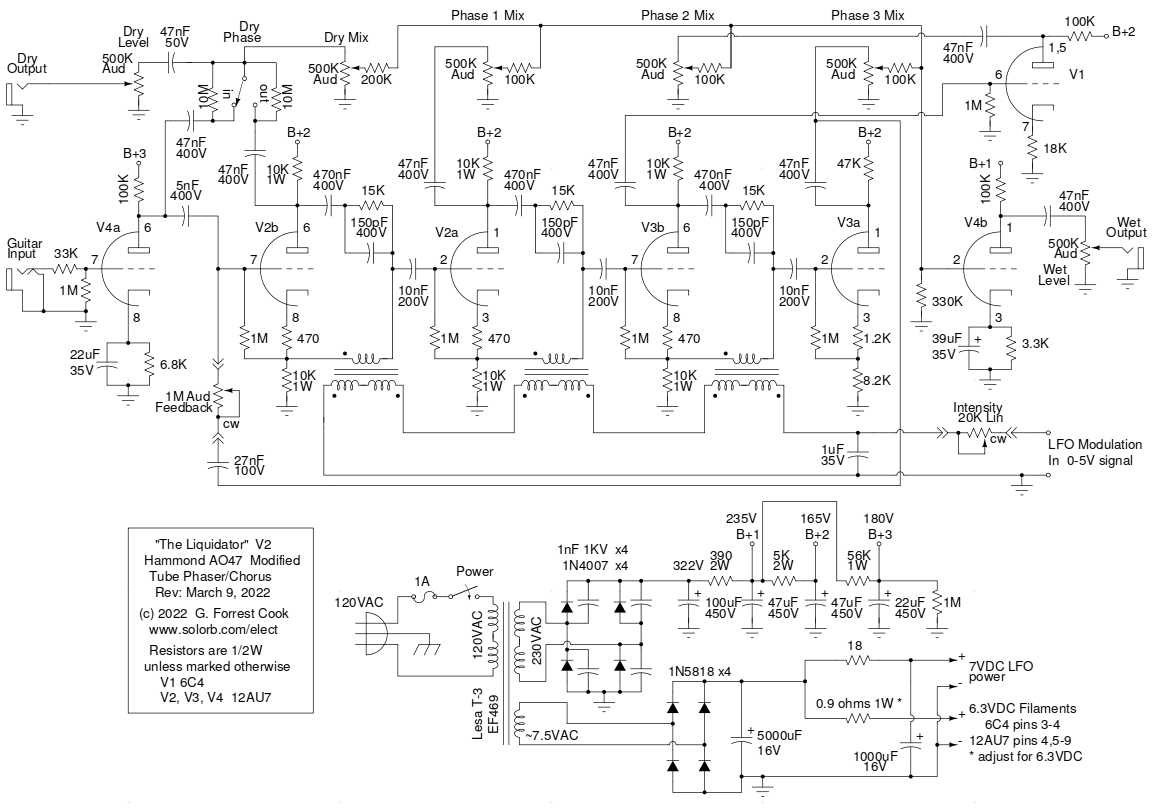
V4a is wired as a High-Z input class A guitar preamp stage, it is similar to the input stage of many tube guitar amplifiers. A Dry signal tap comes from V4a. V2b also produces a Dry signal output, but with the opposite phase. The Dry Phase switch selects between the two signals for different sounding effects when mixed with the phase shifted signals.
The Hammond triple transformer array is the most important part of this circuit. Three identical tube stages (V2b, V2a, V3b) are biased by the 470 ohm cathode resistors and operate as adjustable phase shifters. The two primary windings on each section of the transformer is wired in series, but out of phase. This allows the low frequency modulation wave on the transformer primary windings to vary the transformers' core reactance while cancelling the modulation wave so that it does not show up in the audio output.
The 10nF output capacitor on each stage sees a signal that varies somewhere between the cathode circuit (in phase) and the plate circuit (out of phase), depending on the transformer's input current. Each successive stage adds more phase shift to the signal. It *may* be possible to replace the Hammond triple transformer with three standard transformers, although this has not been tried. A set of three 120V dual primary, 24V dual secondary split bobbin transformers would probably work if the secondary windings were connected in series and out of phase for the modulation side and the 24V windings were used on the audio side.
V4b is used as a summing amplifier (mixer). It receives its input from the clean signal and three phase shifted signals. The output from V4b is sent to the output jack via the output level potentiometer. Note that the cathode capacitors on V4a and V4b are fairly low values and attenuate the lower frequencies. The capacitors can be increased in value for a sound with more bass.
The clean signal can have its phase inverted by the Dry Phase switch, this causes the effect to move in the stereo mix and produce some cancellation when it is in the out-of-phase position. The resistors across the Dry Phase switch discharge the nearby capacitors in order to prevent a loud audio thump from happening when the switch is flipped.
The Feedback control is used to feed some of the third stage phaser signal back to the input of the first phaser stage (v2b). The control changes the shape of the circuit's resonance, higher values produce a wah-wah type of sound.
The filaments for the tubes should be powered with 6.3VDC power instead of 6.3VAC, the AC signals induce a low level of hum into the output signal. The filaments can be run on 6.3VAC, but running them on DC was shown to reduce the hum level to nearly inaudible levels. While not strictly necessary, DC powered filaments are highly recommended, especially if you intend to use the liquidator for studio/recording work.
The combined filament current of the four tubes is slightly above 1 amp. Running the 1960s-vintage power transformer on modern 120V mains voltage produces around 9VDC (unloaded) from the bridge rectifier LFO supply circuit. The 1N5818 Schottky diodes should be used in the bridge rectifier since they produce less voltage drop than standard silicone diodes. When loaded with the filaments, the DC voltage drops down to around 7V. A low-value series resistor (0.9 ohms, 1W) was used to trim the filament voltage down to 6.3VDC.
The 4700uF filter capacitor on the DC supply reduces the filament ripple to reasonable levels, an even larger capacitor could be used here. The 18 ohm resistor and 1000uF capacitor filters the DC supply further for powering the LFO circuit. A better solution might be to build a higher voltage DC supply and use an adjustable linear regulator such as an LM2941CT (with a heat sink) to produce a regulated filament voltage, a second regulator could be used to produce the 7VDC for the LFO.
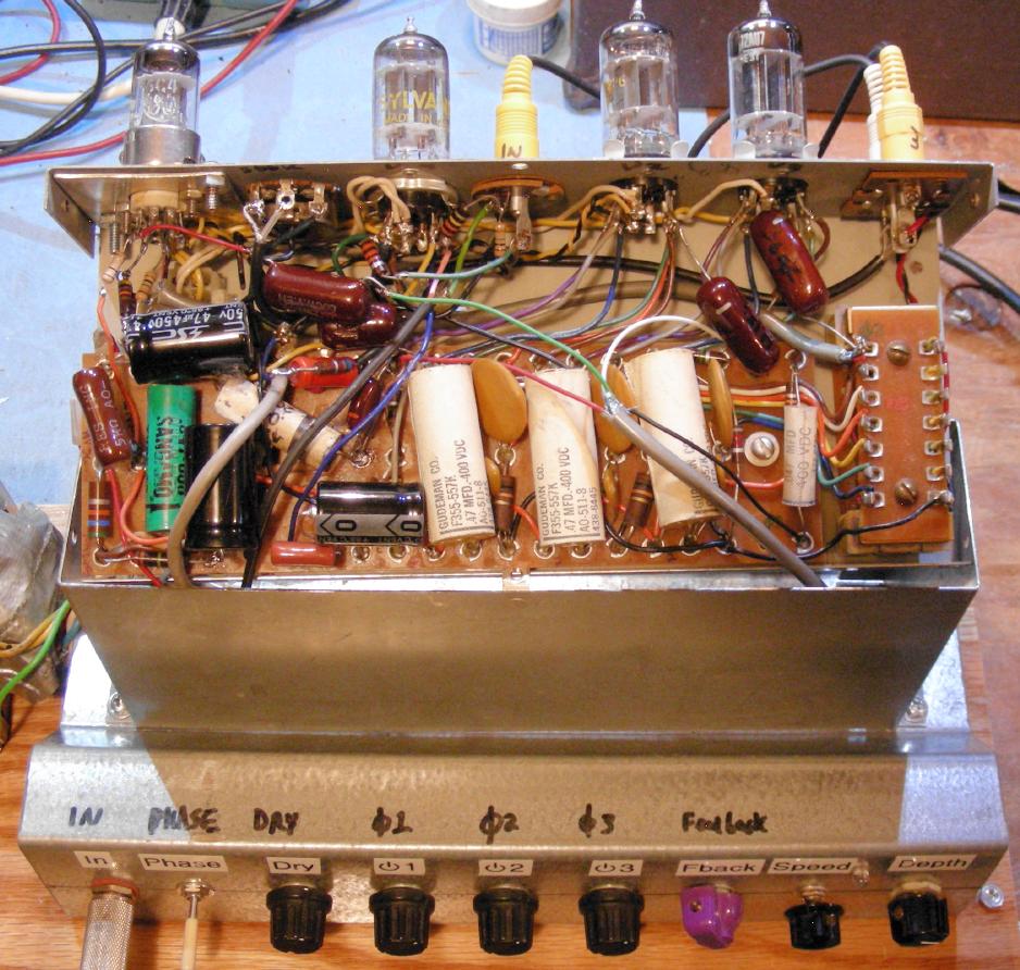
Inside of the Liquidator V2 AO-47 chassis, the triple phase shift transformer is on the lower right side.
The Hammond AO-47 chassis was modified (see above photo). The original electrolytic capacitor was removed from the chassis and a 7 pin tube socket was installed in an aluminum plate that fits in the old capacitor mounting hole. This socket holds V1, a 6C4 triode, which is similar to half of a 12AU7. The second tube from the left was changed from a rare 7247 to a common 12AU7. The oscillator circuitry was removed from this tube (V4) and replaced with the preamp and output amp circuits. The tube designations in the schematic match the original design except for the addition of V1. The tube lineup is: V1, V4, V2 and V3 (left to right).
An "M" shaped metal framing section was used for the lower chassis, this allows the AO-47 box to be slightly recessed. Holes were drilled for the jacks, switches, potentiometers and power cord. A U-shaped metal frame should be constructed to cover the bottom and sides of the chassis. The two bridge rectifiers and first high voltage capacitor are mounted in the lower chassis. The LFO board is mounted on the underside of the lower chassis.
The filament and phaser stage wiring was left in the original state. A fair amount of re-routing was performed on the ground wires. The original electrolytic capacitors should be replaced with new parts, old electrolytic capacitors tend to dry out and have low capacitance.
The power transformer was originally mounted behind the AO-47 box as shown in the top photo. This caused a lot of hum to be picked up by the V4 tube. After some experimentation, the best location for the power transformer was found to be on the lower left side of the AO-47 box with the transformer core oriented front to back. Another way to reduce transformer hum pickup would be to mount the power transformer and rectifiers in an external box that can be moved away from the AO-47 chassis.
The three RCA jacks on the AO-47 box were rewired to provide the input, output and modulation input connections. The rest of the wiring was run through holes between the lower chassis and the AO-47 box. Be sure to leave the wires long enough to allow the AO-47 box to be opened. The 6.3VDC filament voltage was routed through the rectangular plastic connector on the outside of the AO-47 box.
The power supply rectifiers and first-stage filter capacitors are all located in the bottom chassis. All of the 1/4" phone jacks are mounted on the lower chassis using insulated shoulder washers, then wired with coax cable to avoid ground loop hum and noise pickup. The audio signals to and from the mixer pots should all be wired using shielded coaxial cable. One end of the coax shields should be grounded inside of the A0-47 chassis and only one ground connection should be made to the various mixer pots.
The Lesa T-3 power transformer was recycled from some old electronic equipment. A Hammond P-T269EX transformer could be substituted if the rectifier circuit was changed from a 4-diode bridge to a center-tapped 2-diode full-wave circuit. The 390/2W resistor value may need to be changed so that B+1 is around 235V. The P-T269EX can be purchased from Antique Electrical Supply.
A second build of my Arduino V2 LFO is used to modulate the Liquidator. The LFO produces a sine wave which roughly falls in the 0-5V range. The LFO uses an Atmel Atmega 328P microprocessor programmed via an Arduino Uno board to control a MAX522 DAC. The Arduino LFO can be programmed to produce a variety of waveforms such as a simple sine wave or a more complex wave. The code will also fit into the older Atmega 168 microprocessor chip, an Arduino Diecimila board is required for programming that chip. When used for driving the Liquidator, the LFO Bias control should be adjusted to produce around 0.9V at the lowest point of the waveform.
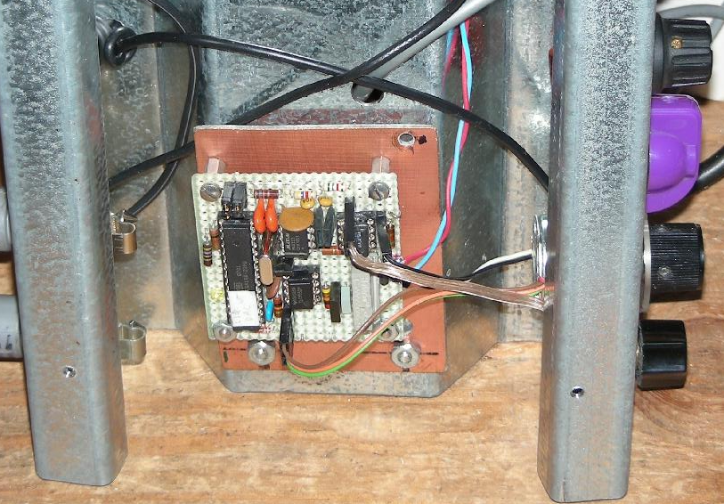
The Atmel Atmega 328P V2 LFO on a hand-wired perf board
Plug an electric guitar or a keyboard into the Liquidator input and connect the Liquidator Wet Output to a guitar or keyboard amplifier. Adjust the Wet Level control to a mid-level setting. When using the Liquidator with a keyboard effect, it may be necessary to set the keyboard's output level control way down or attenuate the keyboard signal with a resistive divider to prevent overloading of the sensitive V4a input amp, see the Modifications section below.
For great stereo effects, plug one amp into the Wet Output and a second amp into the Dry Output, adjust both level controls for a good balance while keeping the amps below the point of overdrive. Stereo is the recommended configuration for this effect, although it is still quite useful as a mono effect.
Many variations on the basic phaser effect are available by adjusting the four mixer controls, the Dry Phase switch and the Feedback control. The Dry signal can be inverted or non-inverted depending on the Dry Phase switch position. Here are a few basic setting suggestions:
When using the liquidator with a high-level keyboard signal instead of a low-level guitar signal, it should be possible to bypass the V4a preamp stage and feed the signal either directly to the 47nF and 5nF capacitors on pin 6 of V4a or to the same caps through a 100K input level pot. A switch could be added to select either the V4a preamp output or a separate keyboard input.
It may be possible to eliminate the V4b stage and connect a 250K output level control in place of the 330K V4b grid resistor. With some re-wiring, V4b could then replace V1, the 6C4, simplifying the build. Keep in mind that the higher level coming out of V4b can be useful for feeding line-level devices such as a mixing board.
The Liquidator is normally set up to be used as a stereo studio effect. To make it work like a typical mono guitar pedal, a standard Carling SPDT foot switch could be wired to connect the output jack to either the input (bypass) or the output (effect).
An interesting modification to this circuit would be to add a second set of mixer controls and an additional output stage to make an even wider variety of stereo effects. A variation on this theme would involve making two 2-channel mixers, one with the Dry and Phase 2 signals and the other with the Phase 1 and Phase 3 signals.
Finally, here is a short audio demo of the Liquidator: Liquidator Demo (flac format, 6MB). It consists of several short takes made with a variety of settings on the Liquidator controls. Recording details: Fender Mex Stratocaster plugged directly into the Liquidator. The stereo signal from the speaker outputs of these amps were sent through 10:1 attenuators in parallel with the speakers, then into an audio isolator and finally into a PC sound card. Audacity was used as the sound recorder. The left channel is the dry signal and the right channel is the wet signal. The amps have fairly worn-out tubes which add some distortion to the signals.
Back to FC's Music Circuits page.