(C) 2005, G. Forrest Cook
This device is a microprocessor controlled waveform generator that can be used for driving a voltage controlled stereo panner for music applications. Panning is simply the movement of a mono audio signal between the left and right channels of a stereo sound system.
The circuit can also be used to drive other voltage controlled modules that are used in analog music synthesis. The output of the waveform generator is a 0-10V DC control voltage.
One of eight waveforms can be selected using an 8 position BCD switch. Waves include: ramp, triangle, sine, cos(x)*sin(5x), damped 4 cycle sine wave, and pseudo random. Other waveforms may be substituted by changing the data in the software's waveform tables.
The waveform generator runs in an asyncronous manner, int can be syncronized with other devices by use of an external (5V logic) sync signal or a manual sync trigger button. The waveform is generator is clocked by an oscillator circuit, the oscillator has three range selections, and an LFO rate control for fine speed adjustments.
The output waveform can be smoothed with an adjustable low pass filter. This can be used to remove the stair steps in the output waveform for a more rounded waveform.
An array of 8 LEDs is included for displaying a coarse version of the output waveform. The LEDs are spread evenly across the front panel to provide an interesting visual effect.
Power Requirements:
+5V DC @ approximately 200mA
+12V DC @ approximately 25mA
-12V DC @ approximately 25mA

Output Levels: 0-10V DC
External Sync Input: TTL level (0-5V) DC, triggers on falling edge
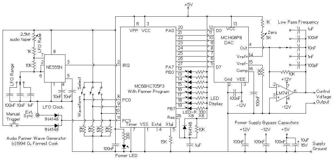
The NE555 timer is wired as an asyncronous rectangular wave clock oscillator. It creates interrupt pulses for the Motorola MC67805P3 microprocessor which cause the program to step through the selected waveform. Note the typo on the schematic, it is not an MC68HC705P3 chip. Coarse adjustment to the 555 is made by selection of three timer capacitors. Fine adjustment is performed by changing a variable resistor.
The LFO clock signal drives the microprocessor's interrupt pin. Each pulse causes the software to advance to the next waveform value in a stored table and send the value to the input side of the DAC, resulting in a new analog value on the output of the DAC. When the end of the table is reached, the software loops back to the beginning. The sync input goes to pin PC3. This signal is either manually generated with a pushbutton, or externally generated with a TTL level signal. When the sync input goes high, the microprocessor resets the to the beginning of the selected waveform table.
One of eight waveforms is selected from eight tables using the 3 bit BCD select switch that is wired to PC0, PC1 and PC2. If a suitable BCD switch cannot be found, three SPDT toggle switches can be substituted.
The microprocessor is set to use its internal clock, the 15K resistor on the Xtal pin is part of the oscillator circuit. The internal oscillator only provides low clock accuracy, this is fine since the timing is gated by the LFO clock. For stable LFO operation, good quality capacitors should be used for the three LFO range parts.
The microprocessor reset circuit involves a resistor, diode, and capacitor. This produces a slowly rising reset signal at power-up, and a quickly falling signal in the event of a brief power outage.
The eight waveform display LEDs are connected to the microprocessor's PB0 through PB7 outputs via some 330 ohm current limiting resistors.
The MC1408P8 DAC receives the waveform level values from the microprocessor's PA0 through PA7 outputs. The DAC converts the digital values into one of 256 analog levels. The output of the DAC is fed through the LM741 low pass filter stage for waveform smoothing. The LPF value is selected by changing the value of the capacitor across the feedback path.
Power is supplied to the circuit from a triple voltage "wall wart" or another source of regulated +5, +12, and -12V DC power. Standard bypass capacitors are connected across the three power supply lines.
The control program pan.asm is written in 6805 assembly language, it needs to be assembled and loaded into an MC68705P3 microcontroller IC using an appropriate programming circuit. See the Motorola MC67805P3 datasheet for an example programmer.
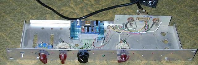
The prototype of this circuit was built on a hand-wired perforated circuit board using wire-wrap technology. The analog components were installed in DIP headers and were connected with wire-wrap wire. 8-way resistor networks were used for the 10K and 330 ohm resistors.
The controls and input/output connections were mounted on a rack mount metal chassis, the wiring was connected to the circuit board with a single dual inline header. The waveform select switches are combined into one rotary switch that produces a 3 bit binary output.
Connect the waveform gennerator to the voltage controlled panner circuit, wire up the mono audio input and stereo audio outputs to the panner. Select a waveform with the 8 position switch. Tune the LFO range and rate controls for the desired panning speed. Adjust the low pass frequency switch for the desired smoothness. Play with the various controls until a good panning sound is heard. The 8 LEDs are programmed to display an approximation of the output waveform.
It is advisable to observe the control voltage output on an oscilloscope in order to become familiar with the effect of the various controls on the output signal.
If the Manual Trigger button is pressed, the waveform output will stop and a new wave will start when the button is released. The external trigger input works in a similar manner. A 0-5V logic level is used for the External Sync input, the waveform output will stop when the input is at 5V and will a new wave will start when the input goes low.
This effect is featured on my Soundtrack for a Low-Budget Sci-Fi Movie audio CD.
This project inspired two more LFO waveform generators: Arduino LFO V1 and Arduino LFO V2, both of them use more modern Atmel processors that are much easier to program than the MC68705P3.
Back to FC's Music Circuits page.