(C) 2009-2020, G. Forrest Cook
This project uses an Arduino development board and a DAC0808 8 bit parallel DAC to produce arbitrary low frequency oscillator (LFO) waveforms. These waveforms are useful for driving a tremolo/vibrato circuit in a guitar amplifier such as the Lil Tiger or a phaser/chorus effect such as the Liquidator. The second version of this project improves on this design by using a serial DAC chip and an analog speed control. This circuit is a descendent of my older waveform generator project.
The initial version of this project was build using a now-obsolete Arduino Diecimila development board (with an Atmel ATMEGA168 processor) and an Arduino prototype shield for the DAC and associated parts. A newer Arduino Uno board with an ATMEGA328P chip should work. The original assembly can be seen in the photographs of the Lil Tiger project. The second generation version of the LFO was built using just the Arduino's Atmega 168 processor chip on a stand-alone hand-wired perforated circuit board. The microprocessor should be programmed on the Arduino board then moved to the standalone LFO board.
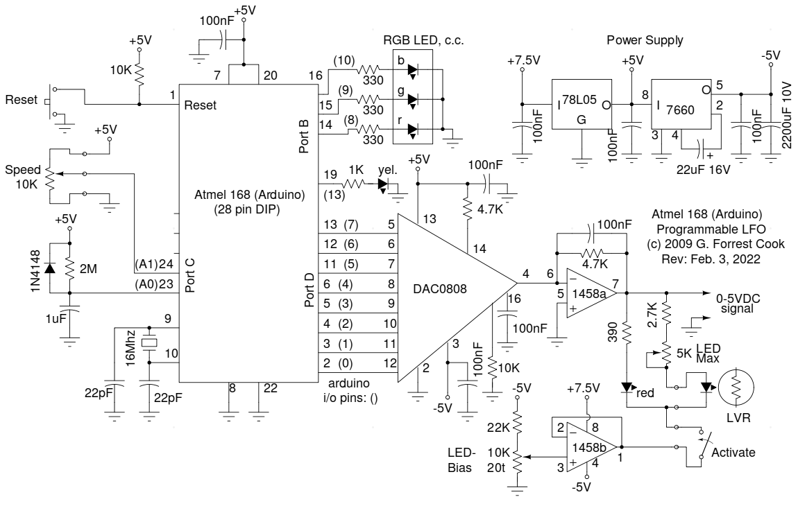
The 7.5VDC power to the board comes from a full-wave Schottky diode bridge rectifier and filter capacitor that is connected to the 6.3VAC filament winding (closer to 7VAC) of a vacuum tube power supply. The 7.5V is regulated down to 5V using a 78L05 regulator. The 5V supply is inverted to -5V with an ICL7660 IC. The +5V and -5V supplies power the processor, DAC and op-amps.
The DAC is an MC1408P8 or DAC0808 that is connected to Port D (out0-out7) on the Arduino. The DAC output drives half of a 1458 dual op-amp wired as a low-pass current to voltage amplifier. The 1458 drives a front panel display LED and an LED/LVR opto-coupler. The other half of the 1458 creates a negative 1.4V bias for driving the negative side of the LEDs. The bias is set so that the LED is just turning on when the DAC is set to output zero volts.
An R-C delay is connected to analog input 1 on Port C, this allows the software to determine if the board was powerd on for the first time or reset manually. The yellow LED on the Arduino port 13 is used to indicate the selected table number, it blinks one, two or three times when the Arduino reset button is pressed. The selected wave number is stored in EEPROM and becomes the default on the next power-up. One might wonder why I designed the waveform selection software this way instead of putting a mode test inside of the LFO while loop, it was done for speed. An in-loop test limits the maximum LFO speed below the maximum desired rate.
An optional RGB LED is connected to the Arduino's port E (out8, out9, out10). A unique color is displayed for each of the three waveforms that the board can produce. A 10K Speed control pot is connected to analog input 2 on Port C, the position is read and used to set the waveform clock rate.
Note that the schematic shows the Atmel ATMEGA168 microprocessor running as a stand-alone part. The LFO circuit can also be built around an Arduino development board. Just wire the appropriate Arduino pins, shown as () numbers, between the Arduino board and the DAC circuit. The Arduino board is required for loading the software into the Atmel processor.
The current Arduino "sketch" for this project is LiquidatorDAC.ino, it is loaded with three slightly different waveforms. The three waves are: regular sine, exponentially weighted bottom-heavy sine and inverted exponentially weighted top-heavy sine. The exponential waves can compensate for nonlinearities in devices that use LED/LVR opto-isolators. The three waveforms are limited to 256 steps each, waveforms that are much larger will exceed the available program memory in the ATMEGA168P processor.
The waveforms were generated by this Python language program: sinegen3.py. The program was run and the output wave tables were stored in a file and transferred into the Arduino source code using a text editor.
The sketch has been brought up to date as of 2022, it now compiles under Arduino version 1.8.19.
Back to FC's Music Circuits page.