(c) 1994, G. Forrest Cook
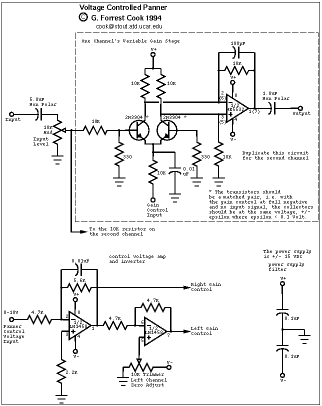
This circuit is useful for audio effects and may be used as a standard plug-in module for voltage controlled synthesizers. The circuit has one control voltage input, one audio input and two audio outputs. The control voltage input can be supplied with a continuously variable voltage from 0V to 10V, 0V pans the signal to the left output, 5V pans the signal to the center, and 10V pans the signal to the right output.
Taking the circuit further, it should be possible to replace the two VCA circuits in this panner with a National Semiconductor LM13700 dual transconductance amplifier IC wired as two voltage controlled amplifiers. See the LM13700 applications notes for details.
The control voltage is fed into the first half of a 1458 op-amp, this stage inverts the signal and sets the offset and gain for the right channel gain control circuit. This signal is then fed into the second half of the 1458 op-amp which inverts the voltage again and generates the signal for the left gain control circuit. The 10K trimmer adjusts the Left channel gain, set it for equal gain from both channels with 5V on the control input. Each audio stage is identical, only one is shown in the schematic.
The pair of 2N3904 transistors form a differential pair that provides voltage controlled gain. The two transistors should be matched, see the note on the schematic. Each gain control stage is fed into an NE5532 low noise audio op-amp that is wired as a differential amplifier.
I recommend building this circuit on perforated circuit board using point-to-point wiring. You can also make a PC board if you have the appropriate tools. Keep the input lead lengths short and provide a filtered +/- 15V power source. It may be useful put the transistors into sockets, this will allow different transistors to be matched without a lot of soldering.
Connect the input to an audio signal source, typically an analog synthesizer. Connect the panner outputs to a stereo amplifier or mixing board inputs. Apply various wave-shapes to the control voltage input, listen to the sound moving around.
Sine waves provide a nice control signal and I have experimented with a microprocessor controlled digital to analog converter (DAC) that can generate arbitrary wave-shapes with interesting results. See my Panner Waveform Generator for details. If you have a modular synthesizer (lucky you), an interesting thing to do is send a triggered modulation wave to the panner, try using the wave that controls the VCF. A triggered, amplitude-modulated sine wave makes for a great effect.
If you want to hear the panner circuit in action, it is used in the CD "Soundtrack for a Low-Budget Sci-Fi Movie" available on my Fractal Music page.
Back to FC's Music Circuits page.