CirKits sells solar power circuit board kits.
(C) 2010, G. Forrest Cook
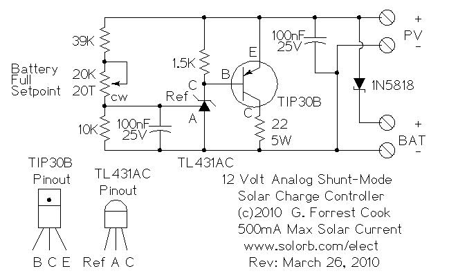
This circuit is an analog alternative to the switching Shunt-mode Solar/Wind Charge Controller. It is one of the simplest ways to regulate the solar charging of a rechargeable battery and requires very few parts. Despite its simplicity, the circuit is relatively efficient. Unlike the all-or-nothing switching shunt-mode controller, this circuit gradually diverts solar power from the battery to the dump load resistor as the battery reaches the preset battery float voltage. As shown, the circuit is limited to 500mA of solar charging current. Higher power systems will be better served with a series switching charge controller.
The circuit shown is set up to charge a 12V battery, it can be modified to support both lower and higher voltage battery systems by changing the value of the 39K resistor.
Solar Panel Open Circuit Voltage: 18V (36 cells)
Solar Panel Short Circuit Current: 0-500 mA max.
Battery Voltage: 12V (nom.), can support other voltages with minor mods.
Battery Capacity: 0.1 to 20 Amp Hours
Solar power is routed from the PV panel through the 1N5818 Schottky diode to the battery. As the charging battery's voltage rises, the TL431AC shunt-regulator IC voltage rises to the point of regulation. As the regulator voltage rises, the TIP30B transistor starts to conduct. The TIP30B connects the 22 ohm load resistor across the PV panel and diverts the excess charging current to the load in order to maintain a constant voltage across the PV panel. During regulation, part of the power is dissipated in the 22 ohm resistor and the rest is dissipated in the TIP30B transistor.
The 1N5818 diode allows PV charging current to flow into the battery during charging, but prevents a reverse current flow into the regulator circuit at night. The diode is a Schottky type which has a lower forward voltage drop (around 0.4V) compared to a regular silicon diode, this improves the efficiency of the circuit.
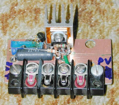
The circuitry for this project was built in the "dead bug style" on a blank piece of copper-clad printed circuit board as shown in the upper photograph. A four wire terminal block was screwed to the circuit board along with a medium sized heat sink. The copper plating on the circuit board was connected to the negative (ground) side of the terminal block. The parts that connect to the negative ground bus were soldered to the circuit board copper on one side and to the other connection points on the other side(s).
The TIP30B transistor was mounted to the heat sink using an electrically isolated heat transfer washer and a nylon shoulder washer which isolates the transistor from the grounded heat sink. An alternative solution would be to use an un-grounded TO-220 heat sink.
A suitably rated fuse in the 1 to 10 amp range should be placed between the battery's positive terminal and the rest of the circuitry. Batteries can hold a lot of energy and a fuse will prevent a fire if any short circuits occur in the wiring. Typical fuses would be the older 3AG 1-1/4" x 1/4" cylindrical types and the automotive ATO/ATC blade types.
The battery should be pre-charged for the easiest alignment. If you temporarily connect the PV panel directly to the battery and put the PV in the sun, the battery voltage should eventually rise above the desired float voltage. If this never occurs, you may need a larger PV panel or a smaller battery.
Connect the PV panel to the charge controller's PV input and connect the rechargeable 12V battery to the controller's battery output. Point the panel at the sun, and monitor the battery voltage with a meter. Adjust the 20 turn 20K potentiometer until the battery reaches the desired float voltage. This is typically around 13.8V for gell-cell lead acid batteries.
Place the PV panel in the sun, the battery will charge until it reaches the float voltage setting. When the battery reaches the float setting, the regulator circuit will dissipate the excess solar energy as heat. The heat sink and resistor may get quite warm when running at the full 500mA solar current level. When using this controller in cold climates, this excess heat can be used to keep the battery warm.
Back to FC's Solar Circuits page.