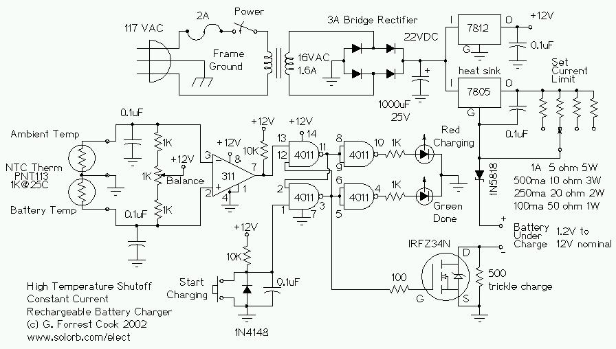
This circuit is for a temperature controlled constant current battery charger. It works with NICD, NIMH, and other rechargeable cells. The circuit works on the principle that most rechargeable batteries show an increase in temperature when the cells becomes fully charged. Overcharging is one of the main causes of short cell life, hot cells pop their internal seals and vent out electrolyte. As cells dry out, they lose capacity. This circuit can quickly charge a rechargeable battery pack without any risk of overcharging. This circuit uses a 22VDC power supply, my improved version 2 circuit will run from a 12VDC supply such as a solar-powered or automobile power system.
The transformer, bridge rectifier, and 1000uF capacitor provide around 22 Volts of DC power to run the rest of the circuit. The 7812 regulator drops this to 12V to run the 311 comparator and 4011 nand gates.
The start switch is pressed to start the charging cycle. This causes the two 4011 nand gates, which are wired as an R-S flip-flop, to go into the charging mode. The Red LED is lit, and the VMOS FET current switch is turned on. Charging current runs though the battery pack. If the battery starts out warmer than the reference temperature, the circuit will not switch into charging mode. Let the pack cool down. When the battery pack reaches a full state of charge, the differential temperature sensor causes the flip-flop to switch off, turning off the VMOS current switch, and lighting the Green LED.
The 7805 voltage regulator is wired as a constant current regulator. This provides a safe maximum charge current for a number of different cell types. The 500 ohm resistor across the VMOS FET sets the trickle charge current which flows through the battery pack after the bulk charging is finished.
The 1N5818 diode prevents the pack from discharging if the AC power is turned off.
The resistor, diode, and capacitor around the start switch cause the circuit to auto-start when power is first applied.
The differential temperature sensor circuit works by presenting two voltages to the input of the 311 comparator. The comparator output switches on or off depending on which input is at a higher voltage than the other. As the thermistors warm up, their resistance drops, lowering the associated comparator input. Since there are two sensors, the room temperature can vary and the circuit will only react to the difference in temperature between the sensors.
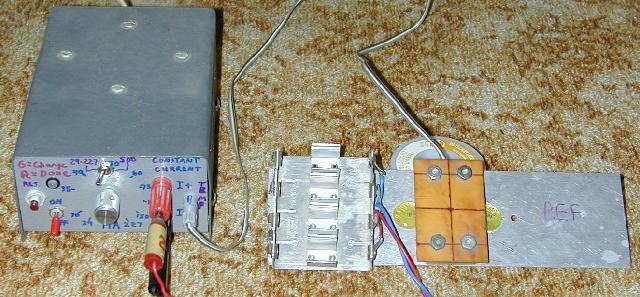
Parts placement is non critical with the exception of the thermistors which should be epoxied to separate aluminum plates and connected back to the main circuitry via a cable with two wires and a shield. The 7805 regulator should be mounted on a heat sink. The current setting resistor may be a high power potentiometer, switch selectable resistors as shown in the schematic, or a single fixed resistor if you only need one current setting.
Be sure to thermally separate the battery and sensors from the other electronics so the heat from the circuitry doesn't affect the sensors. In my prototype, I glued the both thermistors to separate aluminum sheets, approximately 2" X 2" and set the battery sensor on top of the pack being charged, usually with a weight on top. It is important to make sure the batteries have a decent thermal contact to the sensor.
Allow the two temperature sensor plates to reach the same temperature, place a volt meter across the 311 chip's + and - inputs (pins 2 and 3). Adjust the sensor balance trimmer for a reading of -0.02 volts on the meter. Press the reset button and make sure the "charging" LED lights. Warm the battery temperature plate up with your hand and observe that the "done" light comes on.
The Thermistors and most of the other parts in this circuit may be obtained from the larger electronix supply houses such as DigiKey, Mouser and Newark.
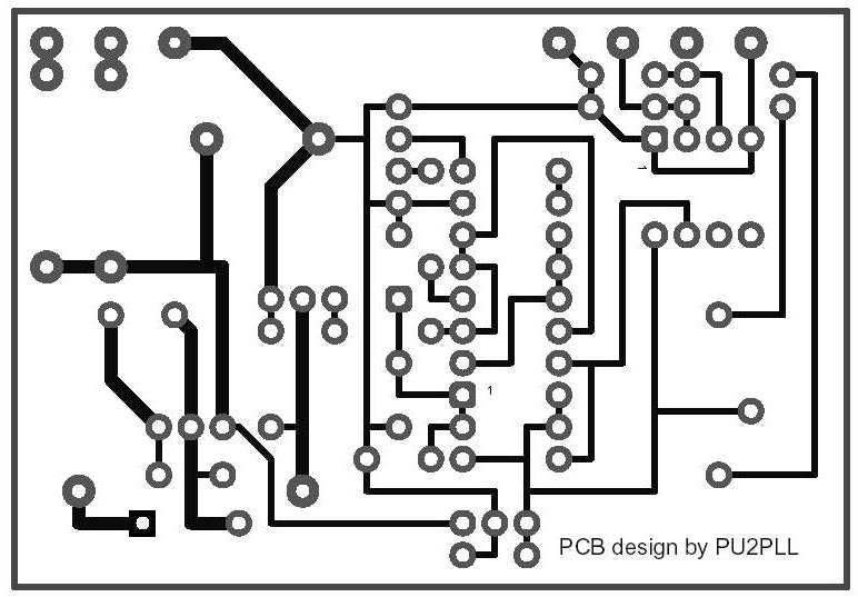
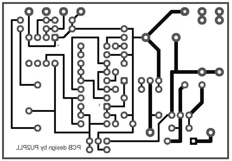
A reader from Brazil has generously submitted the following printed circuit board artwork for this project:
Many people routinely discharge their NICD/NiMH packs in an attempt to prevent the so-called memory effect. The NiCD Memory effect is mostly an urban legend that grew out of a legitimate NASA experiment in which very early NiCD cells were operated in a very narrow voltage region. Modern NiCD cells should not exhibit any form of memory effect. Rechargeable cells all have a limited number of charge/discharge cycles, every time you discharge a cell its capacity and lifetime are reduced. See this article for more on the topic.
A good way to kill NiCd cells is to put a reverse voltage on them. If you incorrectly discharge your NiCd packs as a string, the weak cells will go to zero volts and will then go negative as the stronger cells continue discharging. Putting a negative voltage on a NiCD cell can cause conductive dendrite growth within the cell, that makes the cell become prone to self-discharge.
If you still want to discharge your cells, it is best to only discharge them individually. The cells should Never be drawn down to zero volts. An easy way to accomplish this goal is to put a silicon diode in series with a resistor for each cell, this sets the minimum battery voltage to about 0.7 Volts. For multi-cell packs, a discharger can be built with a multi-cell battery holder and resistors and diodes for each cell.
A typical discharge current is C/5 where C is the amp hour capacity of the cell. For a 500ma AA NiCd a 1N4001 or similar 1A diode in series with 5 ohm 1/2W resistor should give a C/5 (100ma) discharge rate assuming a 1.2V cell, and an 0.7V final resting voltage.
This charger circuit has been working quite nicely for several years now, I have recharged many NICD and NIMH packs repeatedly with no problems. The 1K thermistors may exhibit a small amount of self heating which may result in less sensitivity to battery temperature changes. Changing to 5K thermistors would greatly reduce the effect. The balance pot should be changed to 2K and the resistors on either end of the balance pot should be changed to 3.9K. A better solution would be to use my version 2 circuit.
Back to FC's Electronic Circuits page.