(C) 2009 G. Forrest Cook
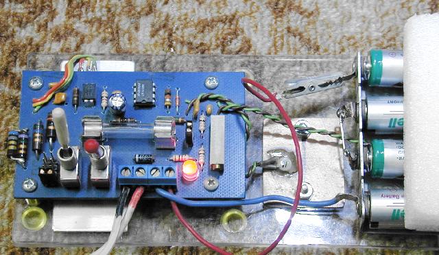
This project includes a number of improvements over my older Temperature Controlled NICD Charger circuit. This circuit runs on 12VDC, allowing it to be used in a car or from a 12V solar power system. Additionally, a current sensor LED verifies that the cells are receiving charging current. Note that the current sensor circuitry is not shown in the circuit board photo above, it was added to the side of the main board via a small perfboard.
The current is adjustable in three steps from 100 to 300mA, allowing fast charging of AA, AAA or other small cells. Battery packs from 1 to 6 cells can be charged with this circuit. NiMH and older NiCD cells are supported. The circuit is protected from reverse input voltage and reversed cells.
12VDC (nominal) power input
Connections for the Battery Under Charge
Power On/Off switch
Charge Start switch
3 step Charge Current Select jumper
Calibrate/[Latch] mode jumper
Temperature sensor calibrate trimmer
Red/Green Charging/Done light
Amber Current Flow light
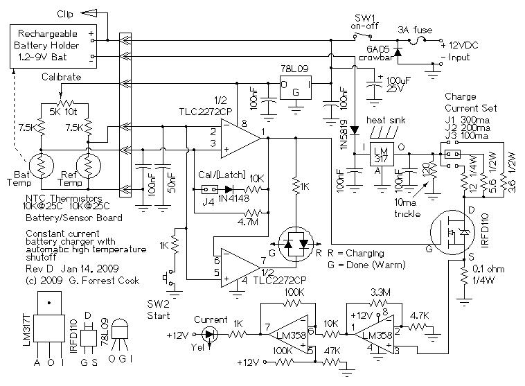
12VDC power is supplied to the circuit from an external source such as a car battery system, a 12V solar power system or a regulated "wall wart" supply. If DC power is applied backwards, the 6A05 crowbar diode causes the 3A fuse to blow, protecting the circuit from reverse voltage. The power switch routes power to the 78L09 voltage regulator and the battery. The 78L09 regulator provides regulated power to the rest of the circuit.
The battery current loop starts with the +12V supply, then runs through the battery and through a 1N5819 reverse voltage protection diode. Current continues through the LM317 1 amp adjustable voltage regulator which is wired as a constant current source, through the IRFD110 power MOSFET transistor, which switches charging current on and off, through the 0.1 ohm current sensing resistor to ground (12VDC negative). The charge current is selected by jumpering one of three current-set resistors on the negative side of the LM317 regulator. The 120 ohm trickle charge resistor always allows 10mA of current to flow through the battery.
The temperature control part of the circuit starts with a matched pair of 10K NTC thermistors. One thermistor is epoxied to a small metal reference temperature plate. The other thermistor is epoxied to a metal battery holder. The temperature sensors are balanced by the calibrate potentiometer. The 100nF and 50nF capacitors across the thermistors cause different start-up time delays to insure that the following circuitry powers up in the off state.
The upper half of the TLC2272CP rail-to-rail op-amp is wired as a latching comparator when the Cal/Latch jumper is present (operate mode), the circuit becomes a regular comparator with hysteresis when the jumper is off (calibrate mode). Assuming the battery is cold and the circuit is in operate mode, the start switch turns the op-amp on for a charging cycle. When the battery temperature exceeds the reference temperature, the op-amp turns off and the diode in the feedback loop latches the op-amp off. The op-amp output also drives the IRFD110 current switch MOSFET.
The lower half of the TLC2272CP simply inverts the output from the upper part of the op-amp, this gives a bipolar drive signal for running the Red/Green Charging/Done light.
An optional current flow lamp was added to the circuit. Rechargeable batteries tend to get corroded contacts which can prevent the charging current from flowing. The lamp provides an indication that the charging current is really making its way through the batteries. The current Flow lamp circuit consists of an LM358 op-amp wired as a current measurement amplifier that monitors the voltage drop across a 0.1 ohm resistor. The LM358 is specially suited for this type of circuit. The output of the first LM358 stage is further boosted and offset by the second LM358 stage. This produces a digital signal that drives the indicator LED through a current limiting resistor. If you don't want to add the Current Flow circuit, replace the 0.1 ohm resistor with a wire jumper.
The circuit was built on a custom home-built circuit board, a hand-wired perf board would also make a good platform for this project. The LM317 regulator is mounted on an aluminum heat sink under the main board, the heat sink should be kept away from the two temperature sensors. The reference temperature sensor is mounted to a small piece of aluminum that is thermally isolated from the battery holder and the rest of the circuitry. All of the sub-components are mounted on a piece of plexiglass or another non conducting material.
Put the circuit in a location with a steady temperature and allow the temperature of the thermistors to stabilize for an hour or so. Remove the Cal/[Latch] jumper and power up the charger circuit. Adjust the 20 turn Calibrate trimmer a little bit past the point where the Charge/Done light turns red. Put the Cal/[Latch] jumper back.
The charger should only be used in a cool location with a fairly constant temperature. Install the batteries to charge in the battery holder, start with the negative side of the socket and connect the alligator clip to the + side of the last cell. Put a piece of insulating foam over the battery holder to keep the warmth in the battery. If the battery is already hot, allow it to cool down before starting the charge cycle. The Charging/Done light should now be green.
Push the Start switch and the Charging/Done light should turn red. The Current Flow light should turn on, if it doesn't, try reseating the cells in the holder. After some amount of charging, the battery will warm up, the Charging/Done light will turn green and the battery charge cycle be finished. If you want to equalize the weaker cells in the battery, allow the pack to cool down then run another charging cycle, the second cycle should not take very long.
Back to FC's Electronics Circuits page.