(C) 2013-2016 G. Forrest Cook W0RIO
|
|
This project involves the construction of a three-tube ham radio CW (morse code) transmitter for the 40 and 30 meter amateur radio bands. The tube set includes a 6AU6 preamp, a 5763 driver and a 6L6GC power amp. Output power is around 20 watts on 40 meters with a 500V B+ supply. The transmitter is driven by an external DDS VFO and can operate in full break-in (QSK) mode. Your author frequently uses this transmitter to communicate from Colorado to stations on the East and West coast of the US using a simple dipole antenna.
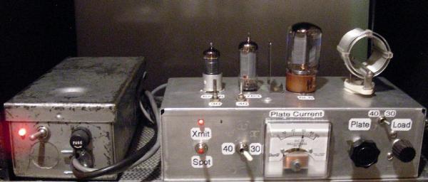
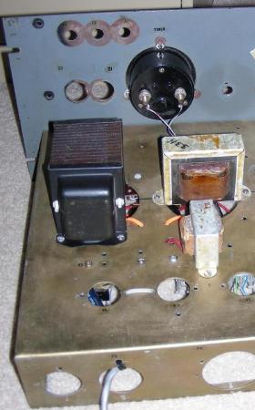
The most recent version of the transmitter runs on a 500V B+ supply and uses a 6L6GC tube for the final amplifier. This tube can handle 500V on the plate and produces around 18 Watts of output power on 40 meters. The new power supply is shown in the third photo. An older version of this transmitter used a 350V B+ supply and produced about 10W of output power. The original power supply is the grey box in the top photo. The lower voltage supply would work with smaller output tubes including: 6V6, 6L6, 6L6G, and 1619 which is the metal military version of the 6L6. The top photo shows the transmitter using a brown-base 5881 which was later changed to a 6L6GC. Other beam-power output tubes including television sweep tubes may be used in this transmitter with appropriate wiring changes.
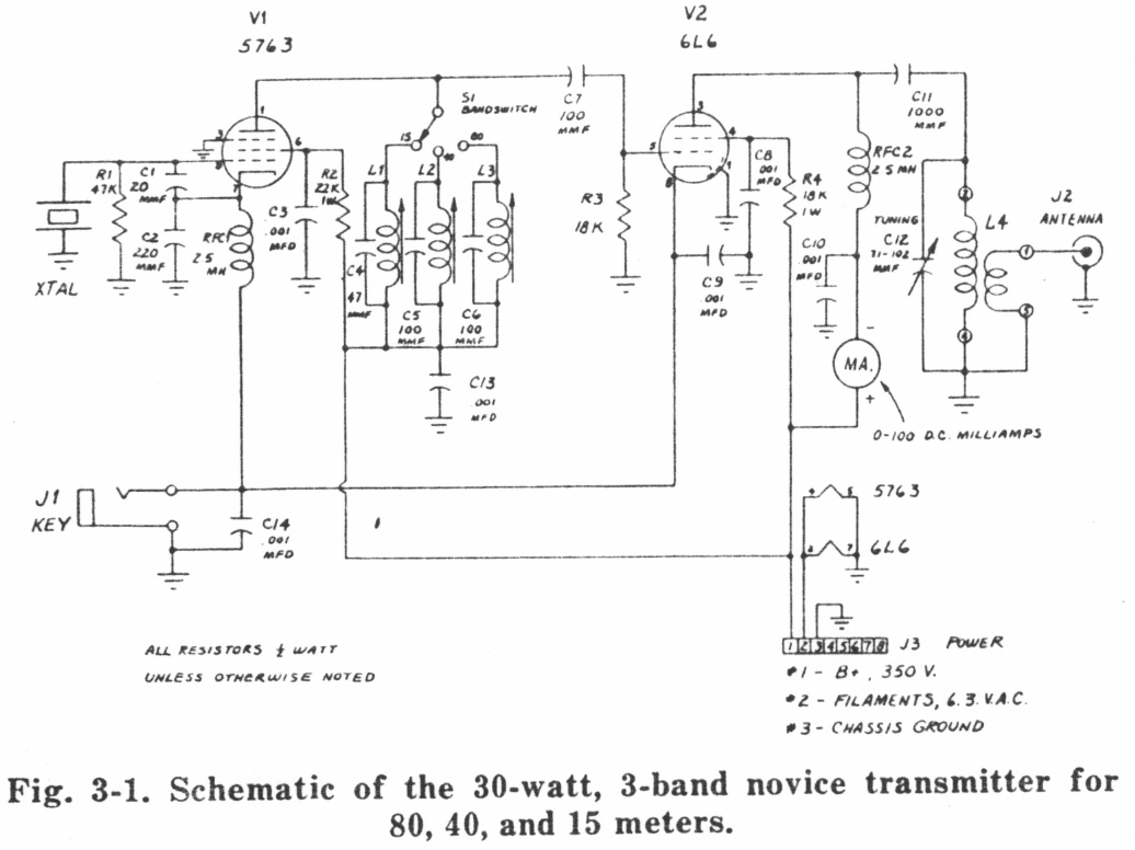
The transmitter was originally a copy of a design found in the 1967 book easy-to-build Ham Radio Projects by Charles Caringella, W6NJV (original schematic). The original circuit was a simple MOPA (Master Oscillator, Power Amplifier) design that used a 5763 pentode and a metal 6L6 beam power tube. It was crystal controlled and worked on 80, 40 and 15 meters. The original output tank used plug-in tuned tank coils with small link coils for coupling to the antenna. That design was highly susceptible to generating harmonic radiation if it was not properly tuned. The output circuit was changed to a more modern PI filter configuration by adding another variable capacitor and removing the link coil connections. Harmonic output is now at least 35dB lower than the fundamental output signal and this can be further improved with a low-pass antenna tuner.
The external VFO is based on a 1990s vintage A&A Engineering Direct Digital Synthesis (DDS) board driving a NE5205N 20dB buffer amplifier IC. The VFO has frequency agility, excellent stability and low phase noise. Unlike a keyed crystal oscillator, the DDS VFO produces a chirp-free signal.
The transmitter's keying input is opto-isolated and is driven by a TTL-level keyer. The keying circuit is a solid-state design that features waveshaping for a click-free signal. Remote signal quality reports have been been very positive. With QSK T/R switching and a DDS VFO, operation of this transmitter is quite easy. This transmitter is compatible with my Modular CW Transmitter Prototyping System.
The March, 2014 version of this circuit had a few changes based on the comments of Jim, N2EY in the QRZ.com homebrew/kit forum. These changes include higher voltage ratings for the plate capacitors, cathode bypass capacitors directly connected to ground, a 10 ohm RFI parasitic reduction resistor on the control grid of the 6L6 and a safety choke on the output tank. The recommended grid current meter was omitted due to a lack of space on the front panel.
This project involves the use of potentially lethal high voltages including 120 VAC and 500 VDC. The project should only be taken on by someone who has experience working with high voltage circuitry. The power cord should always be removed and the power supply capacitors should be discharged before working on the transmitter.
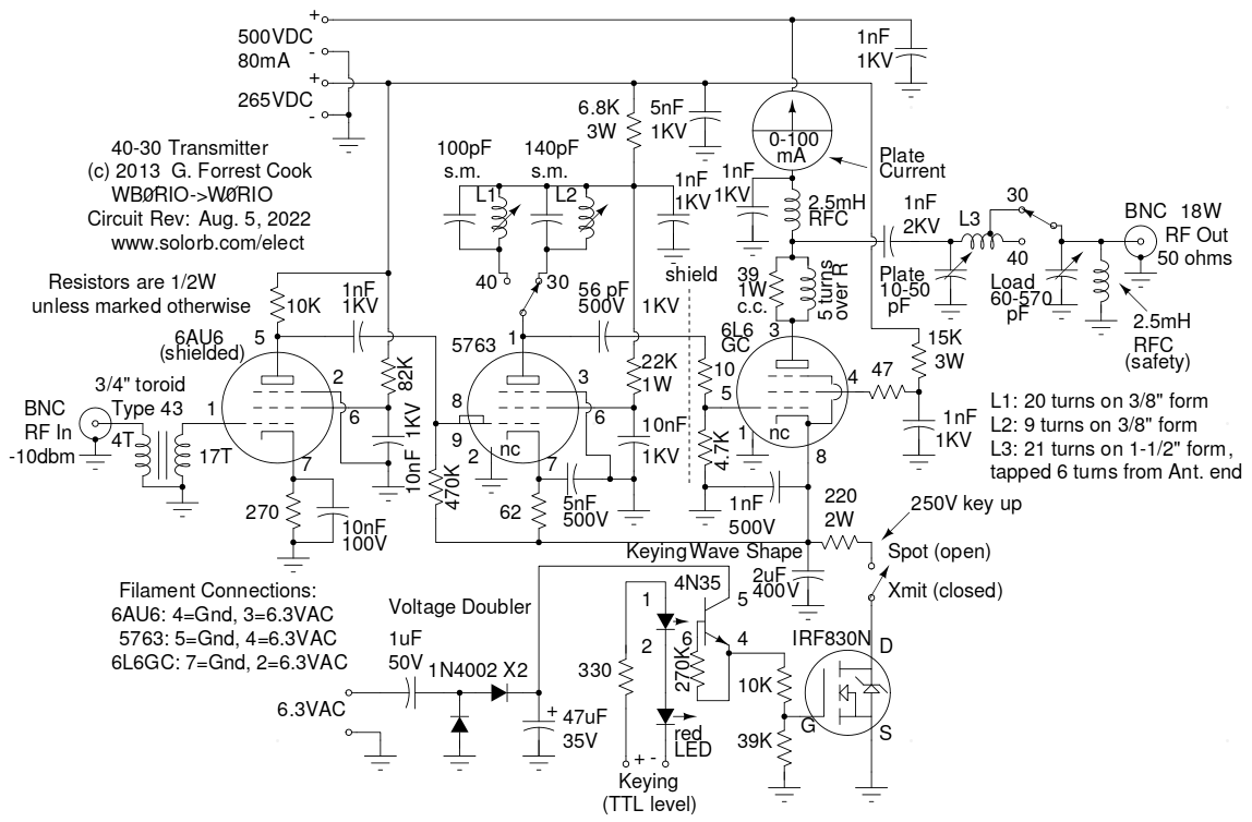
A low-power (around -10dbM) RF signal is sent to the RF input jack. This drives an RF step-up transformer made from a broadband toroid core, which in turn drives the grid of the 6AU6 pentode. The toroid coil was made with #24 gauge PVC insulated solid wire, wound on a 3/4" type 43 ferrite toroid form. The toroid could be replaced by a 1nF capacitor and a 1M grid-leak resistor to ground if you have a sufficiently powerful VFO signal. The 6AU6 is wired as a broadband class-A RF amp, it boosts the input signal enough to drive the 5763 tuned amp.
The 5763 pentode is wired as a tuned class-A RF amp, the tuned circuit on the plate side can be switched between 7Mhz or 10Mhz. Coils L1 and L2 were from the original transmitter, they were Miller coils. I don't know what type of tuning slugs were used, but the 40 meter slug had red paint and the 30 meter slug (formerly 15 meter slug) had no paint. It might be more practical to wind both coils on hollow 3/8" forms with #24 gauge enamel coated wire, then put a combination of silver mica capacitors and ceramic compression trimmers across the coil to achieve the desired resonance.
Note that the 5763 stage can act as a frequency doubler with no circuit changes. My DDS VFO has a maximum output frequency of around 7.5 Mhz, when transmitting on 30 Meters (10.1 Mhz), the VFO is set to 5.05 Mhz and the 5763 stage doubles that to produce 10.1 Mhz. A slightly higher VFO drive level will be required when the 5763 stage is used as a doubler.
The cathode of the 5763 stage is keyed along with the 6L6GC stage, this keeps the tubes cool during key-up periods. The B+ line to the 5763 is current-limited by the 6.8K, 3W series resistor. This allows the tube to run cool while providing plenty of drive power (around 1W) for the 6L6GC.
The 5763 is somewhat of a rare tube these days, it is a medium power VHF pentode that was popular with ham radio builders in the early 1960s. Other small pentodes should work fine here. A 6CL6 (9 pin) or 6AG7 (octal) pentode would be good substitutes, they should work without any component value changes (not tried). The tube socket wiring would need to be changed to accomodate different tube pinouts.
The 6L6GC amplifier stage boosts the signal up to around 20W. The 6L6GC plate circuit has a VHF snubber network consisting of a low-value carbon composition resistor wrapped with a few turns of wire. This prevents spurious VHF oscillations from taking place. The 2.5mH RF choke and 1nF disk capacitor keep the plate RF energy out of the meter and B+ lines. The meter is used to monitor the plate current. The 47 ohm grid stopper resistor on the 6L6 screen grid counters pentode negative resistance effects and the associated short-duration spurious oscillations (dynatron oscillations) that can produce key clicks and wider than desirable bandwidth.
The output network consists of a standard peaked PI lowpass filter. This matches the high-impedance of the 6L6GC plate to a 50 ohm antenna feedline. The output tank coil (L3) was from the original transmitter, it is a B&W 40JEL plug-in coil with the 30 meter tap connected to the unused pin. The B&W coil had an output link coil that is no longer used. A 1-1/4" i.d. PVC pipe connector wrapped with 18 gauge tinned copper wire would make a good substitute The light yellow type of PVC (CPVC) is known to be less lossy at radio frequencies compared to white PVC. See my Little Chickadee Transmitter and Magic Eye Tube Wavemeter projects for examples of home-made tank coils.
The cathode keying circuit uses an opto-isolated high voltage IRF830N MOSFET transistor that pulls the cathodes of the 5763 and 6L6GC stages to ground. A 220 ohm resistor and 2uF capacitor are used to "soften" the rising and falling edges of the RF output waveform, this reduces clicking and produces a signal that is easy to copy. The Spot/Xmit switch interrupts the keying signal, it allows the VFO to power the 6AU6 stage. This produces enough of a signal to hear the transmitter in the receiver, but not enough signal to overload the receiver or interfere with other stations. For builders who want to key this transmitter directly with a straight key, a key jack can be wired in place of the IRF830N MOSFET, additional circuitry may be required to key the VFO so that there is no back wave signal.
The 6.3VAC filament supply is run through a voltage doubler circuit to provide gate drive voltage for the IRF830N. The gate drive is switched on and off with a 4N35 opto-isolator. The 39K resistor shuts the MOSFET off when the gate drive signal is off.
The red LED in series with the 4N35 LED serves a double purpose. It provides a visual indication of keying and also allows a TTL-level signal to be used to drive the transmitter. A TTL logic zero is still high enough to turn on the IR LED in the 4N35 and the red LED prevents this problem.
The keying signal comes from my All-Ears QSK Timing Generator project, that circuit also provides signals for operating the T/R relay, muting the receiver and muting the VFO. The keying + line goes to the All-Ears +5V bus and the - line goes to the All-Ears inverted TX output. The QSK timing circuit also provides a key-up mute signal for the DDS VFO. If you do not require QSK (break-in) operation, any keyer that produces a TTL-compatible output will work with this transmitter. A straight key can also be used, just wire it so that it switches a source of 5-6 VDC to the keying input.
The Power Supply for the 40-30 transmitter is a modified version of the "Economy Power Supply" featured in the ARRL handbooks. It produces 265VDC for the driver section of the transmitter, 500VDC for the power amplifier tube and 6.3V for the tube filaments.
The transmitter was built into a 3"x4"x10" aluminum utility box. Holes were punched for the tube sockets and drilled for the other components. The meter hole was cut by drilling a series of small holes and fitting to size with a nibbling tool and a metal file.
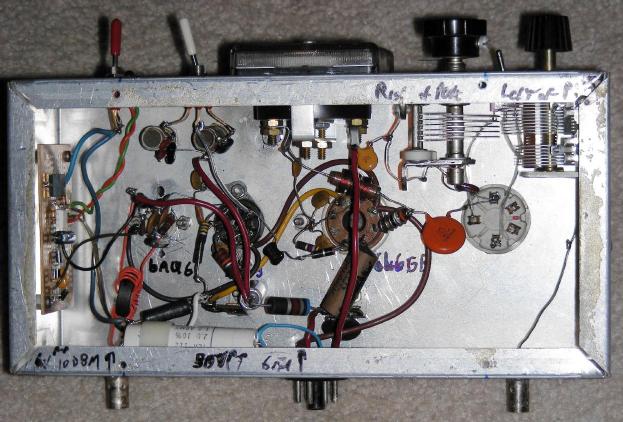
The components were installed and wired with a typical RF wiring style using short leads wherever possible. A small prototyping circuit board was used to hold the voltage doubler and keying circuits, it was mounted on the inside of one of the box sides. External connections include BNC jacks for RF input and output, an octal plug for the power connection and a 3.5MM stereo jack for the keying LED circuit. Only the tip and ring connections on the 3.5MM jack were used so that the keying circuit remains isolated from the rest of the transmitter.
In its original version, the circuit had a strong RF feedback path between the 5763 driver tube and the 6L6GC output tube, causing an undesired self-oscillation at some output tank tuning settings. This problem was fixed by installing a piece of sheet metal on the top of the box between the tubes. A socket with a metal tube shield would be a good choice for the 5763. The box should have a metal bottom plate for electrical safety and reduction of harmonic radiation. To further reduce unwanted harmonic radiation, the 6L6GC tube and the output tank coil should be enclosed in a perforated metal cage.
The external antenna relay uses two reed relays for QSK operation. They are mounted in a deep electrical light switch box with a solid cover plate. Three BNC connectors were mounted on the side of the box. The main relay is a mercury coated SPDT reed type. It switches the antenna between the receiver and the transmitter. The other relay is a normal SPST type, it shorts out the receiver RF input during transmit to prevent front-end overloading. Both relays have 5V coils that are driven in parallel by a transistor. A 1N4001 diode is connected directly across the coils to prevent kickback spikes and a 2N3904 transistor is used to interface the TTL-level driving signal to the relays.
The power supply was built into a separate metal box, the power line to the transmitter is run through a shielded cable that plugs into the back of the transmitter.
A well-stocked junk box is the first place to start, your author scrounged many of the parts for this project from discarded electronic devices. Tubes, tube sockets and power transformers can be found at Antique Electronic Supply or on eBay. Other parts can be purchased from Mouser, Newark, Jameco or Digi-Key.
Before going on the air, the L1 and L2 circuits should be adjusted for peak output power in the middle of each CW band, typically 7.045 for 40 meters and 10.125 Mhz for 30 meters. Connect the power supply, VFO and keying signals to the transmitter. The output line should be connected to a 50 ohm dummy load through an SWR meter.
Set the two band switches to the 40 meter position and set the VFO to 7.035 Mhz. An oscilloscope that is lightly connected to pin 5 (grid) of the 6L6GC will help here. Apply power and activate the keying line. Adjust the L1 tuned circuit for a peak waveform on the oscilloscope. Remove the oscilloscope. Open the Load capacitor to the least capacitance setting. Adjust the Plate capacitor for peak RF power on the SWR meter. Adjust the Load capacitor until the RF signal just starts to drop. Re-adjust L1 and the Plate capacitor for peak RF output power.
Change the VFO to 10.125 Mhz and set the two band switches to the 30 meter position. Repeat the above procedure while adjusting L2. Once L1 and L2 have been peaked, they should not require any further adjustment. Adjusting the 30 meter coil on my transmitter made the output rise slowly below the peak power point, then fall rapidly. The best adjustment was just below the peak on the slow-rising side.
It is fairly straightforward to modify this transmitter to work on more amateur radio bands. The latest modifications to the transmitter allow it to work on the 15 and 17 meter bands as well as 30 and 40 meters. Adding the new bands required changing the SPDT band switch on the 5763 pentode's plate circuit to a rotary switch and adding tuned circuits for each of the new bands. Be sure to keep the wiring to the new tuned circuits as short as possible. The 40 and 30 meter plug-in tank coil on the 6L6GC plate circuit can be un-plugged and replaced with the with the 15 meter coil from the original W6NJV design, the whole coil is used for 17 meters and a tap has been added a few turns from the end for 15 meters.
The 5763 pentode works well as a doubler to convert a 5.05 Mhz VFO signal to 10.1 Mhz, however it does not work well as a tripler for converting 6.03 Mhz to 18.1 Mhz or 7 Mhz to 21 Mhz. It is best to use a VFO which generates the desired output frequency directly. The DDS VFO that I use has a maximum output frequency of 7.5 Mhz, so external solid state tripler circuits are used for the 18 Mhz and 21 Mhz bands.
Traditional multi-band transmitters used a single tank coil and a switch or clip lead between the antenna side of the coil and various tap points to effectively shorten the coil. This approach lowers the Q factor of the tank coil due to the shorted turns and may result in lower output power compared to using multiple tank coils, the big advantage of this method is that band changing can be done with a switch. The variable capacitor components on the tank circuit should work down to 3.5Mhz and up to 21Mhz or higher. Additional capacitance should be added in parallel to the capacitors if operation on 1.8 Mhz is desired.
A ham radio license is required to transmit in the ham radio bands. Connect the transmitter to an antenna such as a 40 or 30 meter dipole and set the VFO to the desired frequency.
The tank capacitors should be tuned up prior to operation on the air, preferably into a resistive dummy load. It is advisable to monitor the transmitter's output waveform by plugging an oscilloscope into the monitor output connector. The scope should display a clean sine wave if everything is tuned correctly. An external SWR meter can be used to peak the transmitter's output power while connected to an antenna.
The best operating point usually involves tuning the plate capacitor to the point where the plate current dips. This coincides with the highest output power. The antenna-side load capacitor should be increased in value to the point where the power just starts to drop. This is the point where the output filter increases the attenuation of the unwanted harmonics. The load capacitor may have a peaking response depending on the antenna used.
Once the transmitter has been adjusted, find an unused frequency and start calling CQ until you get a response, or answer another ham who is calling CQ. The QSK capabilities of this transmitter make operation effortless and fun. This transmitter has been used for many QSOs since it was built. It always gets good CW quality reports, not counting the operator's fist.
Back to FC's Ham Radio Circuits page.