(C) 2016 G. Forrest Cook W0RIO (formerly WB0RIO)
|
|
This project involves the construction of a modular high voltage power supply that can be used to power a variety of vacuum tube ham radio transmitters. The supply produces 6.3VAC for running tube filaments, 265VDC for powering tube driver stages and 500 VDC for powering the final amplifier stage. These voltages may vary depending on the load drawn from the supply and the power transformer used.
The output voltage and current depends on the ratings of the power transformer, a transformer with sufficient ratings should be chosen for the needs of your particular transmitter. This version of the power supply was built using mostly surplus components including the transformers and chokes. New rectifier diodes and filter capacitors were used in the circuit to ensure reliability.
The surplus power transformer that was used can produce 300-0-300 VAC at around 100mA and 6.3VAC at around 3A. The supply is sufficient for producing about 50 Watts of DC input power, which is typically enough to produce around 25 Watts of RF output. This supply has been used to power my 40-30 CW Transmitter.
The energy efficiency of this power supply is very good for tube technology. The switched ballast regulator, lack of rectifier filaments and primary buck winding all reduce the average power usage. After an hour-long Morse code QSO, the power transformer was cool and the glow tubes were just slightly warm.
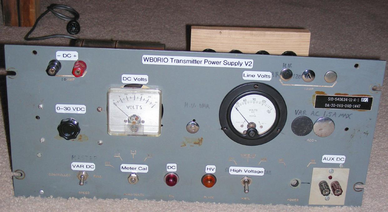
The high voltage power supply (right side) shares the chassis with a variac-controlled 0-30VDC/10 Amp supply that is on the left side of the chassis. The two supplies are completely separate, except for a common AC power input. The variable DC supply is useful for powering high current filament loads. There is also an AC line voltage meter on the front panel and an Auxilliary DC output connection that is derived from the filament circuit.
This project involves the use of potentially lethal high voltages including 120 VAC, 600VAC and up to 700 VDC. The project should only be taken on by someone who has experience working with high voltage circuitry. The power cord should always be removed and the power supply capacitors should be discharged when working on the power supply.
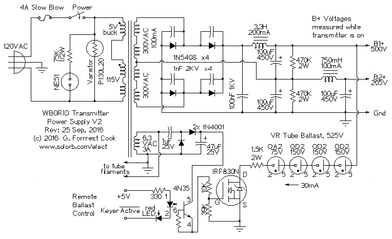
The power supply is a modified version of the "Economy Power Supply" featured in the ARRL handbooks. It produces 265VDC for the driver side of the transmitter, 500VDC for the transmitter's power amplifier (under load) and 6.3V at 3A for the transmitter's tube filaments.
The input of the power transformer uses the 5V rectifier winding in a buck-mode to reduce the secondary voltages by a few percent. This allows older 115V transformers to produce the correct filament voltages when they are run on 120V mains. The 130V varistor on the transformer primary provides the first stage of protection against transient voltage spikes that may come in on the power line. Spikes can be multiplied by the transformer and may damage the rectifier diodes. A neon bulb pilot light in series with a current limiting resistor is connected across the transformer primary.
The power transformer has a 600V/100mA center-tapped high voltage winding that drives a bridge rectifier and feeds a choke-input LC filter for the 500V output. The 1nF capacitors across the rectifier diodes prevent transient voltage spikes from damaging the diodes. The 100nF capacitor on the output of the bridge rectifier helps to filter out any high frequency line noise that makes its way through the transformer. The center-tap of the transformer feeds the center of the high voltage capacitor bank, then is filtered by a second LC filter to produce the 265V output voltage.
A pair of 470K 2W resistors are connected across the HV output to act as a minimum load as well as a capacitor discharge path. A unique feature of this supply is the voltage regulator tube ballast string. The VR tube ballast partially regulates the B1+ line and greatly reduces power spikes in the transmitter's output envelope. Four glow-tube regulators are wired in series with a current limiting resistor to produce a minimum load for the power supply at 30 mA. When the transmitter is sending, the B1+ line is drawn down to 500V by the load of the transmitter and the VR ballast tubes dim.

The VR tube ballast is also (optionally) cathode-keyed by an isolated IRF830N high voltage MOSFET transistor. The MOSFET circuit is driven by an opto-isolated signal from the Morse code keyer and associated All-Ears QSK Timing Generator. A few seconds after transmission stops, the !Active line goes high and the VR tube ballast is turned off. This reduces the B+ idle current and improves the overall power efficiency of the supply. Switching the ballast regulators off also helps to lengthen the life of the VR tubes.

Note that when the VR tube ballast is turned off, the B1+ line will rise to around 700VDC and the B2+ line will rise to around 350VDC. The first Morse character sent when the transmitter is no longer idle will start with a higher envelope resulting in a slight "ping" at the beginning of the transmission. The VR tube ballast will absorb some of this initial voltage spike. Subsequent Morse characters will be regulated as long as the keyer Active signal is valid.
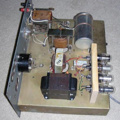
All of the components were mounted on a heavy-duty rack-mount iron chassis that was originally part of some vintage WWII surplus equipment. The transformers and chokes were separated from each other and mounted at right angles to minimize magnetic interaction. The HV bridge rectifier circuit was wired on a multi-point bakelite terminal board and that was mounted above the chassis with plastic screws and an insulating fiberglass plate to minimize the chance of high voltage arcing and breakdown. All of the high voltage connections were rounded and smoothed with plenty of solder, sharp points can bleed HV and cause arcing.
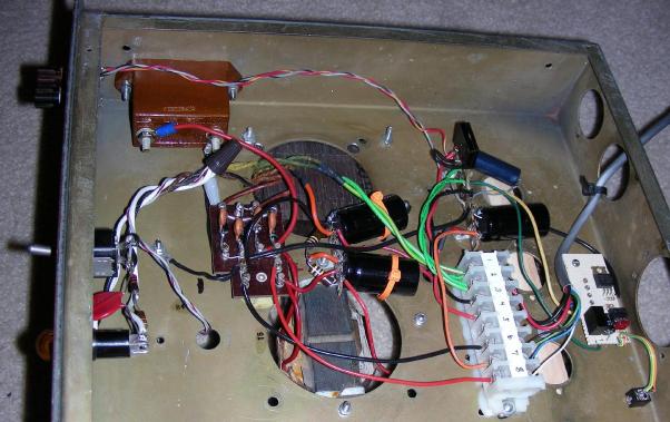
The remote ballast control circuit and its associated low voltage DC power supply were mounted on a perforated board under the main chassis. The remote ballast control connection uses an isolated 3.5mm stereo phone jack. All of the power output lines run to a heavy-duty compression style terminal strip. The power lines feed to the transmitter via a multi-wire cable with a shielded octal socket on the transmitter end.
The VR ballast string was built on a piece of 3/4" pine with four 1-1/8" holes drilled and filed to fit the tube bases. The tube pins were connected by a series of jumper wires that were built with repurposed pins from an old Molex connector and heat shrink tubing. Octal sockets would be a better choice for mounting the VR tubes, but your author ran out of sockets and there were not enough pre-drilled holes in the chassis to accomodate the four tubes.
Operation of the transmitter power supply is fully automatic. Just turn the supply on, let the transmitter filaments warm up, tune up the transmitter and start communicating with other radio Hams.
Back to FC's Ham Radio Circuits page.