
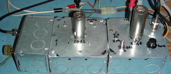
Front: local oscillator module, Rear: preselector, RF preamp, mixer, AF amp modules
(C) 2020, G. Forrest Cook W0RIO
Front: local oscillator module, Rear: preselector, RF preamp, mixer, AF amp modules
The preselector, RF preamp and mixer modules of the Meadowlark receiver
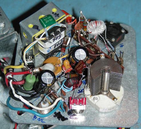
Inside of the Meadowlark mixer module, note the isolated tuning capacitor on the lower right.
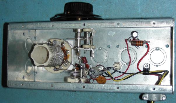
Inside of the Meadowlark local oscillator module
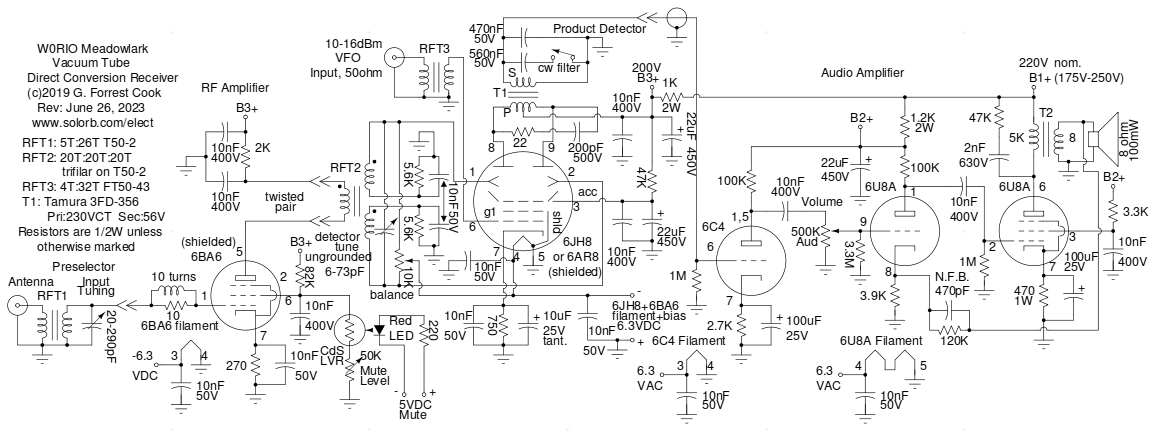
Schematic of the Meadowlark direct conversion receiver
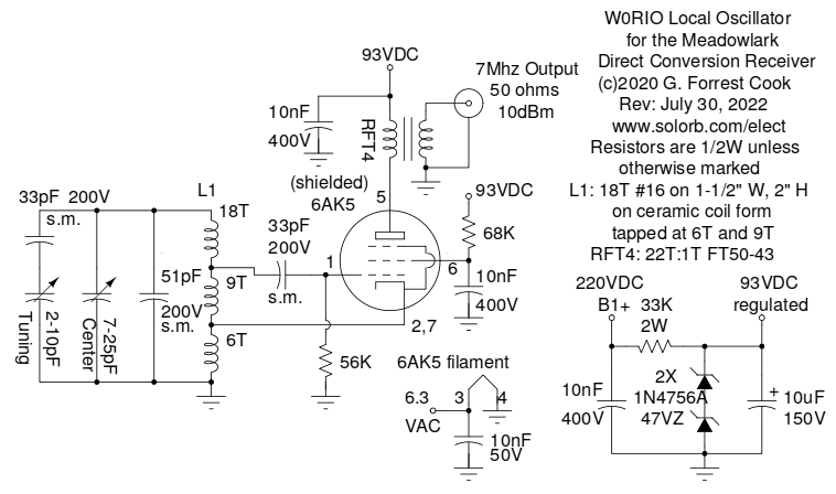
Schematic of the Meadowlark receiver's Local Oscillator (VFO)
This project is my second attempt at making a vacuum tube direct conversion receiver for ham radio uses. It is a direct descendent of my House Finch Direct Conversion Tube Receiver project and uses the RF amplifier (modified) as well as the audio amplifier from that project. Performance is greatly improved compared to the House Finch design. The receiver was assembled with individual circuit modules that were built into steel electrical house wiring boxes, box plates and hardware. The Meadowlark name comes from the pleasant sounds that this receiver produces, much like its avian namesake. The Meadowlark uses a total of five vacuum tubes, that can be reduced to three tubes if an external audio amplifier is used.
After doing some experiments with dual-plate sheet beam tubes and building a 6AR8 AM/DSB Modulator, I decided to try building a product detector using a sheet beam tube. The 6JH8 is very similar to the 6AR8, but has higher gain, either tube will work in this circuit. The 6AR8 is most sensitive with a deflector bias of -8V while the 6JH8 is most sensitive with a bias of -14V. Experimentation with both of these circuit showed that the bias voltage is not very critical.
Direct conversion receivers are known for their high quality audio fidelity and can sound as good or better than many superhet designs. This receiver is well suited for the reception of both SSB and CW signals. Direct conversion receivers are less useful for picking up AM signals such as shortwave broadcast stations since they produce pitch distortion if they are not tuned exactly to the transmitter's carrier frequency. Regenerative receivers, such as the W0RIO Piglet or superhet receiver designs tend to be better suited for listening to AM broadcast signals.
Direct conversion receivers also come with a few challenges, including pickup of hum caused by local oscillator leakage and microphonics due to the high level of audio amplification required. This design performs quite well in in regards to hum pickup as long as it is built into a well-shielded enclosure with good isolation between the RF amplifier, mixer and local oscillator. The RF preamp and high-level VFO injection help to minimize the microphonics, which mainly come from the 6JH8 product detector tube.
The other issue with direct conversion receivers is that they pick up both lower and upper sidebands, resulting in more potential interference from stations on nearby frequencies. That has never stopped ham radio enthusiasts from using DC receivers from making many contacts.
This project involves the use of potentially lethal high voltages including 120 VAC and 220 VDC. The project should only be taken on by someone who has experience working with high voltage circuitry. The power cord should always be removed and the power supply capacitors should be discharged when working on the circuit.
The 220V B1+ voltage and 6.3VAC filament voltage both come from an external power supply such as this circuit, it can be built from commonly available modern parts. The supply is set to the 320V (unloaded) high voltage range, it will drop down to 220V under load. The receiver will work with any B+ supply that produces voltage in the range of between 175V to 250V under load.
A 6.3VDC/1A regulated supply is also required for supplying the 6JH8 filament, the 6BA6 filament and the 6JH8 deflector bias circuitry with DC power. If the 6JH8 filament is run on 6.3VAC, a lot of 60 Hz hum will be injected into the audio. The 6BA6 filament will also add a small amount of hum if it is run on 6.3VAC. The DC filament supply consists of a 9VAC/1A filament transformer, a bridge rectifier, a 2200uF/16V capacitor and either a 7806 or LM317T regulator IC that is mounted on a heat sink. The LM317T can be adjusted for a more precise 6.3VDC voltage.
This power supply could also be adapted for use with this receiver with a few changes, it produces a regulated high voltage and a regulated 6.3VDC filament/bias voltage. An external 6.3VAC filament supply would also be required.
The B1+ voltage drives the audio power amp stage. B1+ is lowered and filtered with RC ladder components to produce the B2+ and B3+ voltages for running the audio preamp, mixer and RF amp stages.
Radio signals from a 50 ohm antenna feedline enter the preselector tuned input transformer, which raises the impedance for driving grid G1 of the 6BA6 RF amplifier. The preselector tuning capacitor resonates the input of the RF amplifier with the desired receive frequency. The preselector tunes well below and above the 40 meter ham radio band. The 10 ohm resistor and coil on G1 lower the chance of VHF oscillations ocurring on the 6BA6.
The 6BA6 screen grid is biased positive with a resistor to B3+ and RF is bypassed to ground with a 10nF capacitor. The light variable resistor/LED combination are used for a mute circuit, when the LED lights, the LVR resistance drops and the screen voltage goes down, causing the 6BA6 gain to drop. The 6BA6 cathode is biased with a 270 ohm resistor and bypassed to ground with a 10nF capacitor. The plate circuit of the 6BA6 runs through a short run of twisted pair wire to RFT2 in the mixer circuit. The B3+ voltage is isolated by a 2K resistor and is bypassed to ground with two 10nF capacitors.
The local oscillator (LO) signal comes from an external VFO assembly, the LO signal is fed through a 50 ohm coaxial cable. A pair of impedance matching transformers (RFT3 and RFT4) convert the oscillator signal to a low impedance and back to a high impedance, this is useful for testing the oscillator and the mixer stages independently and helps to keep the LO signal isolated from the rest of the receiver. The LO should be able to provide between 10 and 16dBm of power to the product detector stage.
The local oscillator uses a miniature 6AK5 pentode wired in a modified Hartley oscillator circuit. The modified oscillator tank circuit came from the 1968 RSGB handbook and uses an extra coil tap for the grid. This configuration allows the main LC components to have a higher Q factor with less capacitive loading from the 6AK5 grid and cathode, this improves the oscillator's frequency stability. The tuned circuit uses a high quality ceramic coil form in parallel with a fixed 51pF silver mica capacitor, a variable ceramic band center capacitor and a 33pF silver mica capacitor which is in series with a ceramic tuning capacitor. The values of the tuning capacitor 51pF capacitor and the 33pF series capacitor may need to be adjusted for the components one can find and the desired output frequency center and span. The coil form was originally part of a WWII vintage BC-191/375 transmitter tuning unit.
Power to the LO is stabilized at around 93VDC via a string of two 1N4756A 47V zener diodes driven by a 33K dropping resistor. The 56K grid bias resistor and 68K screen grid resistor were chosen to keep the 6AK5 tube operating at a relatively low power level, this keeps the tube cooler which reduces frequency drift from heating.
The cathode of the 6JH8 is biased to around +7 volts relative to ground by a 750 ohm resistor and AC-bypassed to ground with two capacitors. The cathode bias causes the G1 grid to be negative relative to the cathode. The accelerator element is biased to around 195V and bypass capacitors are used to remove RF and audio signals from the accelerator.
The two 6JH8 deflector elements receive a balanced push-pull RF signal from tuned RF transformer RFT2. The mixer tuning capacitor is adjusted for resonance at the RF input frequency. The RFT2 output side acts like a center-tapped winding for RF due to the two 10nF capacitors to ground, but has two 5.6K resistors in the DC path to ground. This allow the balance potentiometer to create a differential voltage in the range of +/- 3VDC across the two deflector plates. The average bias voltage between the deflector plates and the cathode is approximately -10VDC.
The two plates of the 6JH8 feed a push-pull signal to the primary side of a split-bobbin power transformer, which acts as an audio output transformer. A series-connected resistor and capacitor across the 6JH8 plates works as a diplexer to remove the 14Mhz product from the detector plates. A 470nF capacitor across the audio output transformer produces a broad audio resonance at 620Hz with an upper 3dB drop at 2.5Khz, this helps to narrow the audio bandwidth of the detector to a range that sounds good with SSB signals. The CW switch adds another 560nF across the transformer to lower the peak response to 300Hz, this helps to eliminate high frequency noise and nearby high-pitched CW signals.
The filtered audio signal is fed to the 3 stage audio amplifier circuit. The tube audio amplifier is optional, it can be replaced with an amplified speaker such as the type used for desktop computers.
The Meadowlark receiver was built into five electrical utility boxes which provide a sturdy platform and excellent shielding between stages. As seen in the top photo, the upper set of three boxes include the preselector tuned circuit on the left, the RF amplifier in the middle and the product detector in the right box. The audio amplifier is in a separate box on the upper right side of the photo and the local oscillator is in the large box on the bottom.
The majority of the wiring is built on 4"x4" box cover plates, the type with center knockout hole can easily be modified to fit 7 and 9 pin tube sockets. The audio amplifier's input line is connected to the detector box via a par of 3.5mm plugs and jacks. Numerous holes were marked, punched and drilled to fit the various screw-mounted parts to the box covers.
Note that the product detector's tuning capacitor has to be electrically isolated from the box, it will not work correctly if it is grounded! If you can't locate an isolated capacitor, just mount a grounded chassis capacitor on a piece of plastic and use an insulated shaft coupler between the capacitor and the front panel knob.
All wiring should be kept as short as possible and power wires should be run through twisted pair wiring. The output of the RF amp feeds the detector input via a twisted pair cable. This wiring should be kept as short as possible, it has a 2 pin header on one end for connecting to a pair of matching pins in the product detector box, this allows for easy disassembly.
All of the local oscillator tank wiring was done with #16 gauge wire for mechanical stability and all of the components were securely mounted in a heavy gauge steel box with an aluminum bottom plate. The 6AK5 tube was mounted in a shielded ceramic tube socket to prevent unwanted oscillator radiation. The oscillator tank coil was a surplus part that originally came from a WWII WWII transmitter. The Tuning and Center variable capacitors were also surplus parts. Extra windings were added to the tank coil and the coil was baked at 250 degrees F for 30 minuits to anneal the copper. After annealing, the tank coil windings were secured to the edges of the coil form with hot-melt glue.
The B1+ line and 6.3VAC filament power are fed to the receiver with surplus 4 pin PC power cables. The bias voltage is fed to the receiver with a separate twisted pair wire. The Audio output can be wired directly to the audio amp with a coaxial wire or routed to an external amplifier with a small audio jack such as a 3.5MM type. The audio jack should be isolated from the detector chassis with plastic washers to prevent ground loop hum.
The 6JH8 and 6AR8 tubes were mass-produced in the early 1960s and new old stock (NOS) tubes are readily available on eBay and from vacuum tube dealers. It has little value to tube hi-fi enthusiasts and can be purchased for reasonable prices, $5 for a NOS tube is typical. The other tubes used in this project are also common and inexpensive. The Tamura 3FD-356 detector output transformer is a split-bobbin type that can be found at large electronic distributors such as Mouser, Newark and Digi-Key. Tube sockets and high voltage capacitors can be purchased from various mail-order outlets such as Antique Electronic Supply.
The receiver is simple to use, set the local oscillator to the desired reception frequency and adjust the preselector and mixer tuning capacitor for the highest noise and signal level. A slight amount of de-tuning may help to reduce audio hum. The mixer balance control should be set by disconnecting the antenna and adjusting for the most amount of hiss in the speaker. The balance control only needs to be set once. The CW filter can be switched in and out depending on the type of signal that is being received. Tune the local oscillator up and down to receive different frequencies, if you tune more than about 50Khz, it is a good idea to re-peak the two tuning capacitors.
This receiver works nicely for monitoring the conditions on the 40 meter ham radio band and is stable enough to use for 2-way contacts. After a few minutes of warm-up time, the local oscillator becomes stable enough to monitor narrow-band CW signals for long periods of time. The audio quality is very good and SSB voice signals sound excellent. Keep in mind that the House Finch receiver has no AGC, so don't turn the volume too high if you are wearing headphones.
This receiver can tune to to other frequencies by simply changing the resonant frequencies of the input and mixer tuned circuits and changing the local oscillator injection frequency. It can pick up the 5Mhz WWV time signal by switching a 75pF capacitor across the mixer tuned circuit, the preselector is able to tune down to 5Mhz with no additional capacitance.
The receiver can be used on the 80 meter/3.5Mhz ham band by adding more coil turns and more capacitance on the same two tuned circuits. Higher frequency coverage should also be possible by reducing the values in the tuned circuits. The mixer circuit will lose sensitivity and local oscillator stability may become problematic as the received frequency goes up.
For improved usage with morse code, it would be a good idea to add a second resonant filter between the mixer and audio amplifier stages. This could be done with a simple pot-core inductor and an appropriate capacitor. The resonant filter should be tuned to a fairly low frequency, such as 500hz, to take advantage of the lowpass filter that is already on the detector.
It is possible to use the 6JH8 cathode and G1 elements to make a self-contained VFO, see Fig. 7 of this article for ideas. However, the use of the outboard local oscillator helps to improve thermal stability and eliminates the need for tricky shielding under the 6JH8. It also provides a higher level of oscillator injection power which maximizes the receiver's overall gain.
The 6JH8 can be replaced directly with a 6AR8 in this circuit. The 6JH8 is most sensitive with a deflector bias of -14VDC while the 6AR8 is most sensitive with a bias of -8VDC. Different bias voltages only have a small effect on either tube's sensitivity.
Back to FC's Ham Radio Circuits page.