(C) 2013-2019, G. Forrest Cook
|
|
|
This project is a general purpose power supply for small vacuum tube projects. It can be used for prototyping low power tube devices with one or two small vacuum tubes. It is also useful for powering Ham QRP (low power) transmitters, audio preamps and other small tube circuits.
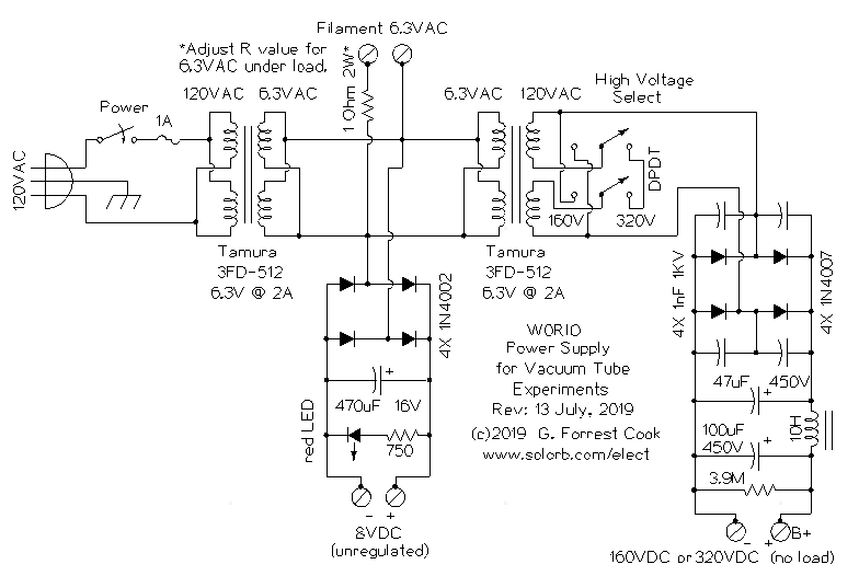
The supply provides a 6.3VAC filament output, an unregulated 8VDC output and a switchable 160VDC or 320VDC (unloaded) output. The high voltage values will be lower during use and will depend on the current used by the load. Two inexpensive and common 6V/12V transformers are used in a back-to-back configuration, eliminating the need for a more expensive high voltage power transformer.
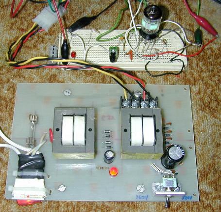
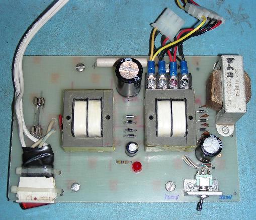
The photo on the left shows the original version of the supply powering an EAM86/6GX8 Magic Eye tube on a prototype board, this eventually became my Magic Eye Tube Wavemeter project. The photo on the right shows the improved version of the supply which includes a 10H 50mA choke and 100uF capacitor for better B+ hum filtering and a 1 ohm 2W resistor for setting the filament voltage to 6.3VAC.
A number of diffent vacuum tube projects have been powered by this supply, they include the 6U8A audio amp V2, the 6U8A audio amp V3, the Little Chickadee QRP transmitter, the AM Chickadee transmitter, the Meadowlark 40M direct conversion receiver, the House Finch 40M direct conversion receiver, the Piglet regenerative receiver and the 6U8A Code Practice Oscillator. The 10H choke and 100uF capacitor can be omitted when powering the Little Chickadee and Code Practice Oscillator projects.
This project uses high voltages including 120VAC and 160VDC/320VDC. The project should only be taken on by someone who has experience working with high voltage circuitry. The power cord should always be removed when working on the supply. It is advisable to short out the B+ line before working on the supply.
The first power transformer converts 120VAC into 6.3VAC/2A, this provides power for tube filaments and the low voltage DC output. The transformer's dual primaries are wired in parallel, the dual secondaries are also wired in parallel.
The DC supply is produced by feeding the 6.3VAC signal into a standard bridge rectifier with a 470uF filter capacitor. The DC supply powers the red power LED and can be used for other DC loads. Note that the DC output rides on a 60 cycle waveform relative to the AC filament winding, it should only be used for isolated DC devices and may not be suitable for use with low-level audio circuits if the AC filament line is also used. The AC filament voltage tends to be higher than 6.3VAC, so a series resistor is included for reducing the voltage to exactly 6.3VAC. The value of this resistor may need to be adjusted to produce 6.3VAC for different filament loads.
The second transformer is reverse-wired to convert 6.3VAC back to high voltage, this is done to provide isolation from the power mains. The second transformer's secondary is switch-selected to run in parallel or series to produce either 120VAC or 240VAC.
The high voltage AC is sent to a 1N4007 bridge rectifier circuit where it is converted to DC. The DC signal is filtered by a Pi filter consisting of a 47uF capacitor, a 10H, 50mA choke and a 100uF capacitor. The 3.9M bleeder resistor insures that the capacitors will discharge after the power is turned off. The DC output is either 160VDC (unloaded) or 320VDC (unloaded), depending on the setting of the output voltage selector switch.
This circuit was built directly onto a piece of bare glass/epoxy printed circuit board material with point-to-point wiring on the back side of the board. A T-square was held against the parts to keep everything oriented correctly. The smaller components were aligned by drawing regularly spaced dots with a Sharpie pen in various locations around the board, then drilling out the holes.
The larger components were placed on the pcb material and the lead locations were marked with the pen. Holes were drilled for each of the lead locations, the components were inserted into the holes and are held in place by the wire connections on the bottom.
Four metal spacers were installed under the board, they can be used to isolate the board from a metal chassis or for mounting to another blank piece of PC board material as shown above. Rubber feet were attached to the lower board. History buffs may notice that the (mostly) blank PC board is a repurposed DEC bus-grant board from a Vax 11/780 computer.
It is advisable to install the finished circuit board inside of a metal case. The case should be connected to the power cord's ground wire if you use a grounded plug. In the above build the line cord and lighted power switch were removed from a defunct coffee machine, note that this uses a non-grounded plug. The high voltage select switch should be mounted on a grounded metal bracket to keep leakage currents off of the switch handle. The 10H choke coil should have its metal frame connected to ground. The two power transformers can also have their frames grounded. All of the high voltage wiring should made inaccessible to prevent shocks and fire hazards.
All of the projects that use this supply receive power via common 4 pin Molex PC disk drive power connectors. Multiple female connectors are attached to the supply so that several devices can be powered at once. The filament circuit uses the yellow/black pair and the high voltage supply uses the red/black pair.
Connect the filament connections to the tube circuit's filamenent connections and the B+/B- connections to the tube circuit's high voltage connections. Set the high voltage selector switch to either 160V or 320V. Power up the supply and the tube circuit should come to life.
Note that the filament voltage will probably be around 8V, depending on the amount of filament current used. A series dropping resistor in the range of 0.5 to 20 ohms at a few watts is used for adjusting the actual filament voltage to 6.3VAC. This resistor is especially important when dealing with fragile antique tubes.
The total power output of the supply is around 12 Watts, power used by the filaments reduces the available power for the B+ supply. A nice side-effect of this is that the B+ supply rises up slowly because cold filaments consume much more current until they warm up. You may be interested in reading about my more advanced Vacuum Tube B+ Delay Circuit.
Back to FC's Ham Radio Circuits page.