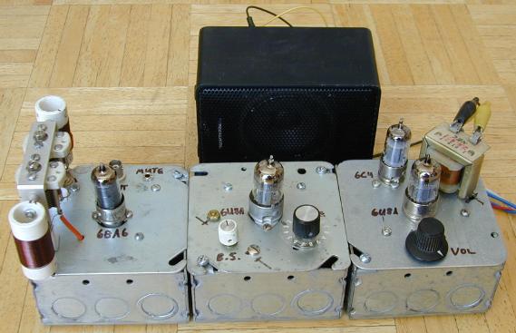
Top View of the House Finch Direct Conversion Receiver
(C) 2012, G. Forrest Cook
Top View of the House Finch Direct Conversion Receiver
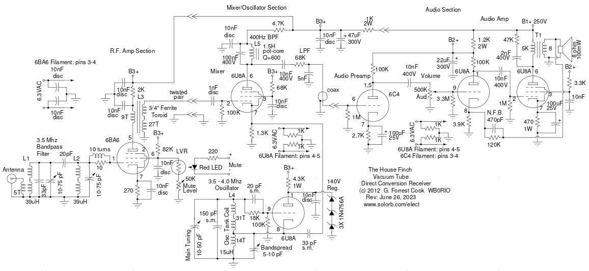
Schematic of the House Finch Direct Conversion Receiver
After building the Little Chickadee 6U8A vacuum tube 80 meter CW transmitter project, your author decided that it would be a good idea to build a companion 80 meter tube CW receiver. A direct-conversion design seemed like a good approach since it is fairly simple and is effective for receiving morse code. Not wanting to reinvent the wheel, the Internet was searched for vacuum tube direct conversion designs. Surprisingly, no other projects were found. The online projects that were found were either solid state designs or regenerative tube circuits.
Nature abhors a vacuum, but not necessarily a vacuum tube so this project was born. Of course, designing something new with vacuum tubes is not an entirely rational pursuit. Rationalizations aside, tube projects are fun, nostalgic and they glow in the dark. This project was a lot more difficult to complete than originally anticipated, but solving the many problems was certainly educational. Those who copy this design should have a much easier time getting the circuit running. It should be farily straightforward to adapt this design to other HF ham bands by changing the resonant sections in the front end filter and oscillator.
My 6U8A audio amp project was already built and was initially used for this receiver. More audio gain was needed, so a 6C4 preamp tube was added, The Version 3 6U8A audio amp is a stand-alone version of the updated audio amp circuit. The 6U8A seemed like a good choice for the mixer and oscillator circuits, that's a typical application of the 6U8A. The 6BA6 RF amplifier tube was added to improve the isolation between the antenna and the mixer stage.
The receiver is divided into three physical sections, 1: the RF filter and amplifier, 2: the mixer, oscillator and audio filters and 3: the audio amplifier. A few extra grid bias resistors and filament hum cancelation resistors were added so that the individual sections can be disconnected and operated in a stand-alone mode. This also allows the sections to be used as stand-alone modules for other projects. An external power supply provides 6.3VAC for the filaments and 250VDC for the B+ line.
This project involves the use of potentially lethal high voltages including 120 VAC and 250 VDC. The project should only be taken on by someone who has experience working with high voltage circuitry. The power cord should always be removed and the power supply capacitors should be discharged when working on the receiver.
The antenna is coupled via a 5 turn winding to a two pole bandpass filter that consists of L1, L2 and the associated capacitors. The bandpass filter's capacitors should be accessible to the operator since they need peaking as the receiver is tuned across the 80 meter band. The output of the bandpass filter is fed to the 6BA6 RF Amplfier stage through a VHS supressing R-L network on the control grid of the 6BA6. The 270 ohm cathode resistor sets the bias for the 6BA6. The 6BA6 plate circuit has a broadband 1:9 transformer for coupling to the mixer stage.
The filament bypass capacitors were found to be necessary to eliminate oscillation in the RF amplifier. An external mute control was added to the screen grid circuit, it uses a red LED coupled with a small light variable resistor (LVR) that can pull the screen towards ground and reduce the RF gain when the transmitter is active. The mute level trimmer control should be adjusted so that the transmitter is audible, but not so loud as to overwhelm the receiver's front end. A variety of 10nF disc capacitors are used in the RF amplifier stage to stabilize the amplifier.
The mixer uses a 6U8A pentode section wired as a product detector. The local oscillator signal is lightly coupled to the pentode's cathode via a 33pF capacitor. The pentode's screen grid is biased with a 68K resistor to B+ and bypassed to ground with a 10nF disk capacitor. The pentode's cathode is biased via a 1.3K resistor to ground. The plate circuit of the pentode uses an audio bandpass LC filter that resonates at around 400Hz.
The coil used in the audio bandpass filter (L5) was a junk box part that was wound on a high Q pot-core. See below for details. The capacitor across L5 should be chosen to produce a peak audio tone at a frequency that is pleasant to listen to. Adjust the capacitor's value according to the coil you use for L5 and your preference of tone. The output from the audio LC filter goes through a DC blocking capacitor and an RC low pass filter, then onto the audio preamp stage. The low pass filter removes a lot of high frequency noise that can cause operator fatigue.
The local oscillator uses a 6U8 triode section wired in the grounded plate configuration. The oscillator output is taken from the cathode (feedback) connection. The tank circuit is resonated between 3.5 and 4 Mhz by a combination of variable (tuning) and fixed capacitors across the coil. The bandspread capacitor is used to fine-tune the received signal.
The tank coil (L4) and associated capacitors will need to be adjusted according to the variable capacitors that you have available. Adjusting the oscillator to cover the desired frequency range should be done with a frequency counter on the oscillator's cathode and a variety of fixed capacitors in place of the 150pF capacitor shown. High quality capacitors and a stable coil form are necessary for good oscillator stability. The three 1N4756A zener diodes and the 4.3K plate resistor provide a regulated plate supply for the oscillator tube, this prevents drift when the transmitter is keyed and when the line voltage changes.
The audio preamp stage consists of a 6C4 triode wired in a standard class A configuration. The 6U8A audio amp article explains how the rest of the audio amplifier works.
The B+ power from the power supply goes to the B1+ line on the audio amplifier, it is isolated and filtered through a 1.2K / 22uF RL filter to make the B2+ power line, this supplies power to the audio preamp and driver stages. The B3+ line is isolated and filtered through a similar 1K / 22uF RL filter before being sent to the mixer and RF amplifier stages. The B3+ line is filtered for RF by 10nF disk capacitors where it enters the mixer and RF amp sections. Hum canceling resistors are used on the filament lines in the mixer and audio amp sections and RF bypassing is used in the RF amplifier.
As with the Little Chickadee transmitter project, the power supply is not shown, it must supply 250 Volts DC and 6.3 Volts AC. The power supply that is used in my Howler Monkey amplifier project can be used for both the transmitter and receiver, a series dropping resistor between the power supply B+ and the receiver's B+ should be used, the value of the resistor should be adjusted so that the receiver's B+ voltage is 250V.
The three modules were built onto 4"x4" electrical utility box covers. The 6U8A tube sockets were installed into knockout holes in the box covers and appropriate holes were drilled for the rest of the components. A number of multi-point terminal strips were installed on each box cover and components were installed with the point-to-point wiring method. All RF wiring should be kept as short as possible in the RF amplifier and mixer sections.
The three box sections were bolted together using pairs of holes that were already in the box sides and doubled-up spacer washers. Circular metal plugs from the box knockouts were drilled out to form the spacer washers. Side knockouts were removed to provide a wiring channel between the boxes and one Romex cable clamp was installed on the back of the audio amplifier box for the connection of the filament and B+ wiring to the power supply.
Filament power is connected to all three sections via twisted-pair wiring. The B+ lines are twisted around ground wires to connect the high voltage power to the boxes, don't just rely on the metal box for the ground. Note that the internal wiring between the modules should be short, but long enough that the box tops can be flipped open for working on the individual sections.
Signal wiring between the receiver sections is somewhat critical. A twisted pair was used between the RF amplifier and the mixer, it should be kept as short as possible. A piece of audio coax cable was used to connect the mixer to the audio amplifier, it should only be grounded on the audio amplifier side to eliminate ground loop hum.
They say that hindsight is 20:20. In retrospect, one change that that would greatly improve this receiver would be to put the oscillator/mixer section into a larger box and use a vernier tuning mechanism on the main tuning capacitor. Tuning the existing receiver is a bit tricky with the layout shown.
The input bandpass filter can pick up the signal from the VFO and turn the receiver into a regenerative receiver when the bandpass filter capacitors are adjusted. The filter should be installed in its own shielded box to fix this issue. Tube shields should also be used on the 6BA6 and 6U8A tubes to keep the RF from the oscillator from leaking back to the input.
A well-stocked junk box is the first place to start, your author scrounged most of the parts for this project from discarded electronics. Tubes, sockets and transformers can be found at Antique Electronic Supply or on eBay. Other parts can be purchased from Mouser, Newark, Jameco or Digi-Key. Home Depot, or any well-stocked hardware store will carry the electrical boxes and plumbing parts.
L1 and L2 consist of 50 turns of #28 gauge enamel coated copper wire on a 7/8" diameter, 2" long form. The coil form is standard 1/2" white PVC pipe. The inductance was measured at 39uH. The coil is mounted onto the variable capacitor assembly with 3/8" standoffs and 14-20 machine screws and nuts. The antenna coupling primary winding on L1 consists of 5 turns of #24 insulated copper wire wound on top of the ground end of L1.
The L3 secondary consists of 27 turns of #24 gauge insulated copper wire on a 3/4" ferrite toroid core. The L3 primary consists of 9 turns of the same wire on top of the middle of the secondary winding. Do not use enameled wire here since the ferrite core can cut through the insulation and short out the coils.
L4 consists of 45 turns of #24 gauge enamel coated copper wire on a 5/8" solid nylon coil form. The total inductance was measured at 15uH. The tap is located 14 turns from the ground end of the coil. It is recommended that L4 be coated with polystyrene "Q-dope" or plastic cement to prevent oscillator instability.
L5 has many turns of super-fine magnet wire wound on the bobbin of a high Q Ferroxcube 3/4" ferrite pot-core. It measured 1.5H with a Q of 600. The primary winding of a tube output transformer or a the primary of a small filament transformer will also work here, with somewhat lower selectivity than the pot-core coil.
Connect an antenna and power supply to the receiver and apply power. Adjust the tuning capacitor to a part of the band that you want to listen to. Tune the two bandpass filter capacitors for maximum background noise. Since this is a direct-conversion receiver, a certain amount of 60 cycle hum will probably be picked up, this can be reduced by careful adjustment of the bandpass filter capacitors. Use the bandspread control to zero in on a CW signal, the morse code notes should peak in volume as the pitch is changed to the center of the audio filter's pass-band. Note that a good antenna and ground should be used for the best signal reception. A 65 foot or longer wire strung as high as possible will work nicely, an 80 meter dipole will work even better.
The All-Ears QSK Timing Generator can be used to tie the House Finch receiver and Little Chickadee transmitter together, it can also drive a T/R relay for switching the antenna.
In the process of building this receiver, a temporary crystal oscillator circuit was used in place of the VFO circuit. The VXO oscillator circuit in the Little Chickadee transmitter will work nicely in that capacity. It should be possible to turn this project into a fixed-frequency WWV receiver by using a 5Mhz or 10Mhz crystal in the oscillator. The VXO adjustment would be required for tuning the AM broadcast carrier to zero-beat. For best AM reception, L5 should be a lower Q coil, or its Q can be lowered by placing a resistor (10K to 100K) across the coil with a switch.
After building this project, your author stumbled upon a 1973 QST magazine transceiver project by Doug DeMaw (W1CER) and Gus Wilson (W1NPG), known as the "Pebble Pulverizer", it used a direct conversion receiver design. The project is available for download at the N6EV Glowbugs page.
My W0RIO Piglet 6U8A Regen receiver is a much simpler 6U8A short wave receiver design, it works quite well for picking up short wave AM broadcast signals.
As of 2019, the House Finch receiver project has been retired and parts of it have been re-used to build the new W0RIO Meadowlark 6JH8 Direct Conversion Receiver, which is a much-improved design compared to the House Finch. The many lessons learned while building the House Finch contributed a lot to the Meadowlark design. Bye-bye birdie, R.I.P. House Finch.
Back to FC's Ham Radio Circuits page.