
(C) 2024 G. Forrest Cook
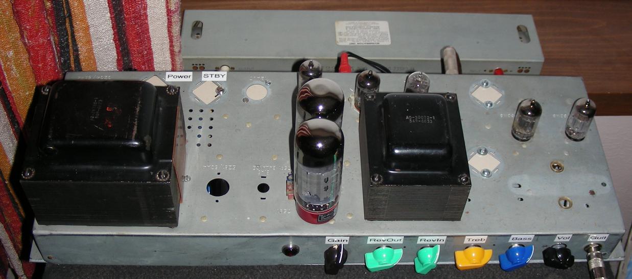
Basserator 2R amp, click for a larger image.
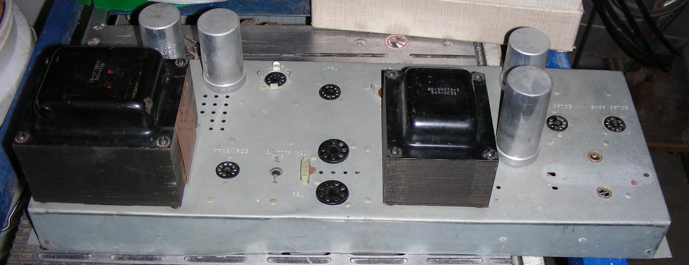
Basserator 2R amp chassis, click for a larger image.
Original Hammond AO-63 amp chassis, click for a larger image.
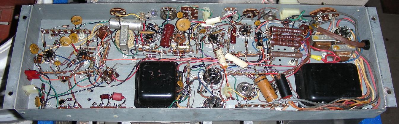
Original Hammond AO-63 amp underside, click for a larger image.
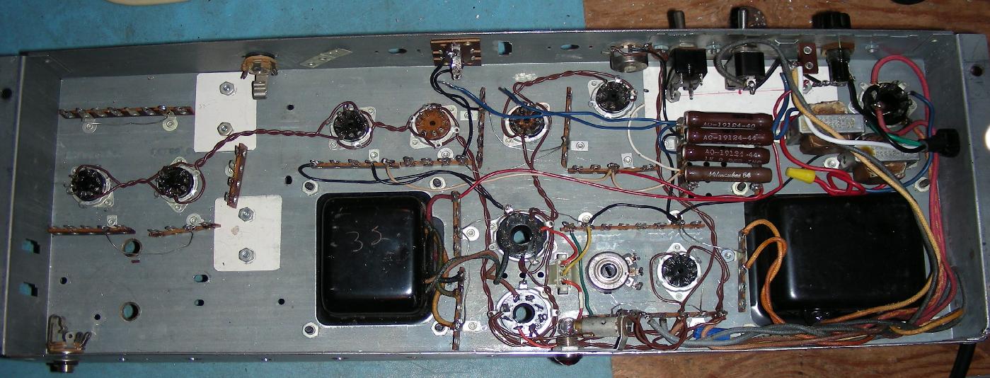
Hammond AO-63 amp stripped and patched underside, click for a larger image.
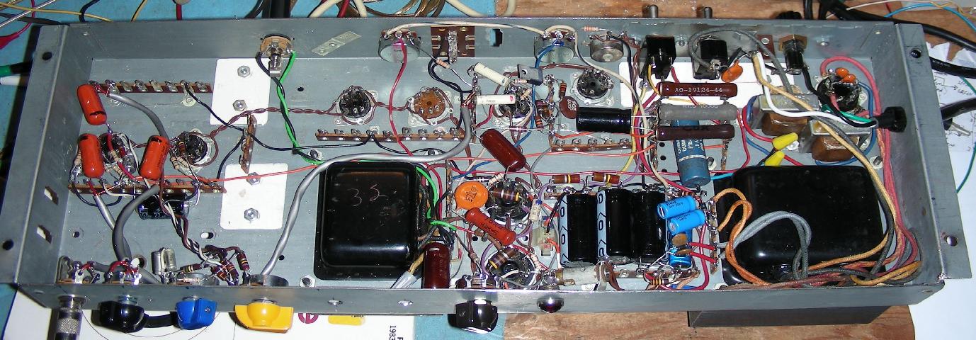
Basserator 1 amp underside (no reverb), click for a larger image.
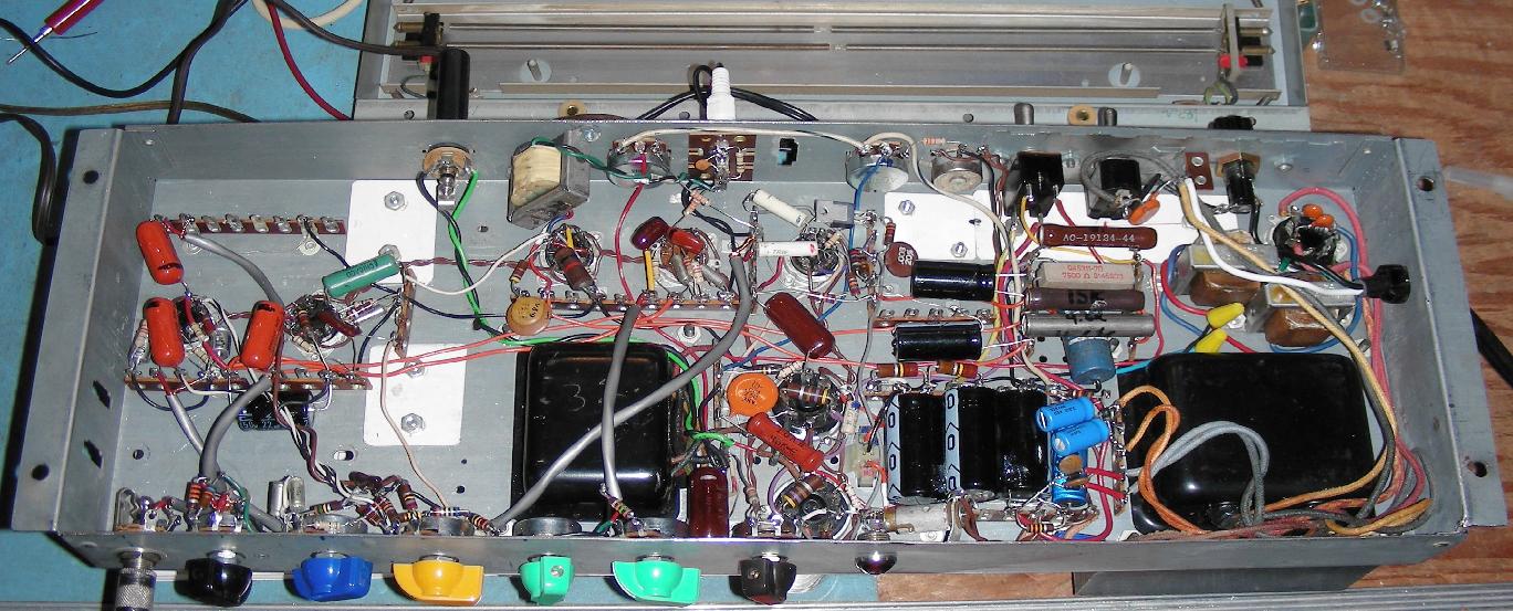
Basserator 2R amp with underside (with reverb), click for a larger image.
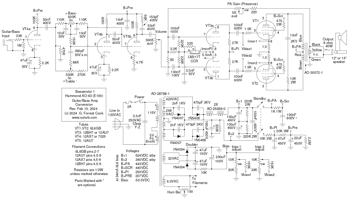
Schematic of the Basserator 1 Hammond AO-63 amp conversion (no reverb)
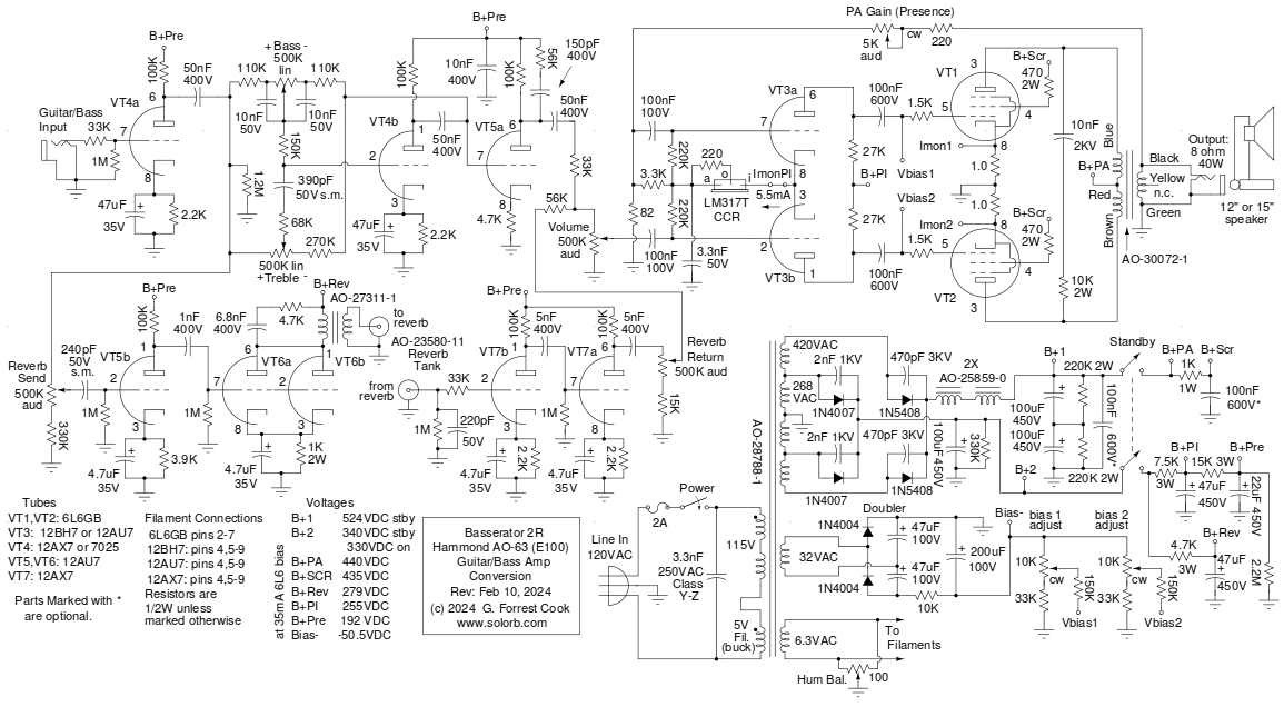
Schematic of the Basserator 2R Hammond AO-63 amp conversion (with reverb)
The Basserator amp involves the conversion of a Hammond AO-63 E100 organ amplifier into a guitar and bass amplifier. In its original form, the AO-63 chassis contains a large power amplifier for the main organ speaker system and a lower-power amp for the reverb channel speaker. In the Basserator amp, the reverb channel output circuitry was removed and the power amplifier channel was modified to use common 6L6GB power tubes instead of the original 7591 power output tubes. 7591 tubes are rare and expensive. The Basserator produces around 40 watts of power into an 8 ohm speaker and has very good bass response.
The Basserator conversion is the eighth, and highest power Hammond amp project that your author has undertaken. It follows the Hammonator 2RVT, the Lil' Tiger 1 and the Spartacus 1. The spare reverb channel output transformer from the Basserator chassis was used in the Spartacus AO-44 amp chassis. That chassis was missing its original transformer when it was purchased on eBay. Both amps used the same AO-24158-0 output transformer.
The Basserator has a number of interesting features including a dual high voltage power supply, a constant-current balanced phase inverter and an active tone stack that uses negative feedback for a wider range of control. The Basserator also includes individual bias controls for the two 6L6GB output tubes. Two versions of this amp are shown, the first is the simple form with no reverb effect and the second includes the additional reverb circuitry. The AO-63 chassis includes a reverb driver transformer and has a number of spare RCA jacks and tube sockets to make this job easier.
This is a fairly high-level project. It takes advanced technician skills to deconstruct and reconstruct the circuitry in guitar amplifiers. Also, there are plenty of lethal high voltages inside of this amp including 120 VAC, 524VDC and 840VAC. The project should only be taken on by someone who has experience working with high voltage circuitry. The power cord should always be unplugged when working on the amp. The circuitry will eventually discharge the capacitors when power is turned off, but it is always a good idea to short out the electrolytic capacitors before working on the amp.
Before building the Basserator circuit, it will be necessary to remove most of the original parts from the tube socket and terminal strip pins. See the photos above to see the before and after images. This process takes a lot of time and patience. The filament wiring was mostly left in place, with the exception of the filament hum balance pot which was moved to a different location to make room for the power and standby switches. The wiring between the power transformer's high-voltage winding and the 5AR4 rectifier tube socket were also left in place, the new 1N5408 diodes were wired across the back of the socket.
The AO-63 chassis includes many small ground wires that connect between the terminal strip ground tags and the tube sockets. These improve the overall ground system and insure that the grounds do not rely on just the terminal strip rivets, which can become oxidized over time. A few extra ground wires were added between some of the previously unused terminal strip ground tags. Be sure that the ground wire between the power transformer's high voltage center tap and the electrolytic filter capacitor bank is in good condition. The power cord ground lead should also have a connection to the grounding network.
Removing the original capacitors, resistors and wires takes a lot of effort and patience. Take your time and take a lot of breaks. Be careful not to damage the tube socket pins. If you do break off a tube socket pin (I did), it is possible to replace a single pin with one from an unused socket. A solder sucker and pointy dental tool were used to remove most of the original solder connections.
The original parts and wires were clipped off of the various pins using diagonal cutters. The solder was melted and vacuumed out of each pin, then the remaining wire pieces were clipped with diagonal cutters to make shorter pieces. The pins were then heated with a soldering iron and the remaining wire pieces were pried off with the dental tool. After the pins were cleared, the dental tool was used to scrape off the solder flux residue. Finally, all of the left-over solder bits were scraped off of the chassis and removed with a vacuum.
The front-panel side of the chassis on this amp was bent during shipping from the original eBay seller. It was straightened out by bending the metal back to its original shape using a pair of sheet metal Vise Grip pliers. All of the original electrolytic capacitor cans were removed and three metal cover plates were cut out and screwed to the chassis to cover the remaining holes. Two unused 9 pin tube sockets were removed and fitted with metal hole plugs. The reverb driver transformer was removed from the inside of the chassis and was re-mounted closer to the dual RCA jacks.
The 9 pin 6CA4 rectifier tube socket was removed to make room for the new electrolytic capacitors. This socket is close to the power transformer and would pick up hum if it were used for an audio tube. The old AC power cord was removed and replaced with a three-wire cord, the original cable clamp was used for the new cord.
Holes for the controls, jacks, switches, fuse and pilot light were marked, punched, drilled and filed smooth. The 1/4" guitar input jack was mounted in a 1/2" hole using insulated shoulder and flat washers. This was done so that the jack could be grounded at one of the preamp terminal strips for the reduction of ground-loop hum.
The Basserator conversion and circuit design was performed with a number of discrete steps. These included:
The AO-63 power supply uses a large AO-28788-1 power transformer. The 5VAC filament winding that was originally used for the 5AR4 rectifier tube was re-wired to be in series with the 115VAC primary winding. This reduces the transformer's output voltages and adapts the transformer to the modern 120VAC line voltage. Be sure to get the phasing of this winding correct by checking the voltage on the 6.3VAC filament winding, it should be lower with the buck winding connected.
The power transformer has dual high voltage output taps. The lower voltage taps are used to produce 340VDC (on standby) for supplying the preamp and phase inverter stages. The higher voltage taps are used to produce 524VDC (on standby) for supplying the power amp. The dual supply improves the overall efficiency of the amp by lowering the amount of voltage drop required from the supply's power resistors.
The higher voltage supply uses large 1N5408 1KV/3A rectifier diodes feeding a pair of AO-25859-0 chokes and a stack of 100uF filter capacitors. The lower voltage supply uses two 1N4007 rectifier diodes feeding a 100uF filter capacitor. Both high voltage supplies are switched on and off by an DPST Standby switch. The high voltages are lowered with series resistors and further filtered by additional capacitors in order to supply the 6L6GB screens, phase inverter and preamp stages. The series resistors have oversized wattage ratings to insure long life.
The power transformer's 32VAC winding is fed to a voltage doubler and a 100uF filter capacitor to provide the two adjustable bias voltages for the 6L6GB grid circuits. The bias voltage ranges can be adjusted by changing the value of the 33K resistors on the ground end of the 10K bias adjustment potentiometers and the 10K resistor between the doubler and 200uF filter capacitor.
The power amp section consists of a pair of 6L6GB beam-power tubes feeding the Hammond AO-30072-1 output transformer. The 6L6GB screen grids are supplied by a pair of 470 ohm grid-stopper resistors and the control grids have similar 1.5K grid-stopper resistors. The grid-stoppers help to tame the tubes by lowering the response to radio frequencies on the control grids and eliminate negative resistance effects on the screen grids. A pair of one ohm resistors were installed between the 6L6GB cathodes and ground for monitoring the cathode currents. The 3 pin Molex connector that is located between the octal sockets was connected to the two cathodes and ground and is used for bias current monitoring.
The PA Gain control acts as a variable negative feedback circuit by feeding the speaker output back to the phase inverter. Note that the original AO-63 circuit had the yellow output transformer's speaker winding center-tap grounded, this lead should be removed from the ground and capped off. The green output transformer secondary wire should be connected to ground.
The phase inverter uses a 12BH7 dual-triode in a current-mirror long tailed pair circuit. An LM317 adjustable voltage regulator is wired as a constant-current source for the two 12BH7 cathodes. The constant-current circuit improves on similar phase inverter designs by insuring that triodes are run at the same idle current and gain. The master Volume control feeds one side of the phase inverter and the gain control feeds the adjustable negative feedback signal to the other side.
The tone control circuit was found on Max Robinson's site (see below), it was modified for use with musical instruments. The tone control uses an active negative feedback circuit to produce a wider range of buck and boost control compared to passive tone control circuits. The active tone control is followed by a 12AU7 gain-recovery stage. The tone stack requires around 500K of resistance to ground on the input side for proper operation. The non-reverb version of the amp uses a 470K resistor to ground and the reverb version uses a 1.2M resistor in parallel with the 500K reverb pot and 330K series resistor which together are around 490K to ground.
The input preamp is fairly basic, it uses a 33K grid-stopper resistor to lower the response to high frequency (RF) signals. The 47uF cathode capacitors in the first two stages and the 50nF plate capacitors are oversized compared to regular guitar amp circuits. This improves the bass response of the amp.
The reverb send circuit starts with the clean signal from the VT4a guitar preamp, which is fed through the reverb send (dwell) control. The VT5b triode boosts the clean signal. The boosted signal is sent to the parallel-wired triodes of VT6, which powers the reverb driver transformer and the reverb tank. All of the coupling and cathode capacitors in the reverb channel were chosen to pass higher frequencies and attenuate lower frequencies. The R/C snubber across the reberb driver transformer eliminates the highest frequencies in order to reduce distortion in the reverb tank.
The reverb return circuit uses two stages of amplification from VT7 to boost the signal up to a level that is suitable for mixing with the output of the tone control circuit. The 220pF capacitor on the input of the reverb return prevents oscillation when the reverb cable is disconnected. The two resistors feeding the master volume control were chosen to give a good balance of clean and reverb signals. The reverb return control produces a boosted reverb mix when it is above about 70% of its full range. The 15K resistor on the low side of the reverb return control works with the 56K mixer resistor to prevent the control from attenuating the clean signal at low reverb return settings.
After building the reverb circuitry, a few of the resistor values in the power supply section were lowered in value compared to the non-reverb version of the Basserator. This compensates for the added DC loads of the reverb circuitry.
Alignment of the amp should be performed whenever a different set of 6L6GB tubes are installed. Measure the idle current of the two 6L6GB tubes by inserting DVM probes into the middle and side pins on the Molex connector that is next to the power tubes. The DVM should be set to measure volts and the current is the same as the voltage shown. The idle current should be somewhere between 35mA (0.035V) and 55mA (0.055V). Higher values will produce more output power and less cross-over distortion while lower values will allow the tubes to run cooler and last longer. A 45mA idle current is a good value to start with.
Set the idle current of both tubes to the same value by adjusting the two bias controls and monitoring the two current test points. There will be a small amount of interaction between the controls. Either bias control should be tweaked a small amount to achieve the minimum speaker hum level when the amp is idle. Adjust the filament hum balance control for the minimum hum in the speaker, this should be near the center of its range. That completes the alignment of the amp.
As with all new amp builds it is a good idea to get the amp up and running with used power tubes. Once you are satisfied that the circuitry is working properly, a new set of tubes can be installed. A set of supposedly matched TAD Red-Base 6L6GC tubes have been tried with this amp, they worked ok, but the bias balance between the tubes produced the minimum hum when one tube was set to 50mA and the other was set to 40mA. JJ brand 6L6GC tubes are another option.
If you happen to be lucky enough to have an AO-63 chassis with a good set of 7591 output tubes, this circuit should work with them. The bias circuit will probably need to be modified to produce different voltage ranges. Using 7591 tubes would save the effort of rewiring the octal sockets for 6L6GB tubes.
The 12BH7 phase inverter tube is recommended, but a common 12AU7 will work just fine in the circuit with no modifications. The 12BH7 provides more headroom for driving the 6L6GB output stage and will have somewhat less distortion than the 12AU7.
A lower-noise 7025 tube can be substituted for the 12AX7 used in the VT4 preamp and tone control stages. The VT4 socket could be replaced with one that supports a metal tube shield, this is optional since the amp is very quiet without a shield. The VT7 reverb recovery tube socket can support a tube shield, this should be installed if the appropriate type of shield is available.
The Basserator is a loud and clean amp with very good low frequency response. This makes it ideal for use with an electric bass guitar. The amp works just as well with an electric guitar. A 15 inch speaker is recommended if you are using the amp with a bass.
Start with the standby and power switches turned off. Turn on the power switch. Wait at least 30 seconds for the tube filaments and cathodes to warm up, then turn the standby switch on. Set the gain control to its mid range, lower levels are good for a clean and tight sound while higher levels are good for a punchy loud sound. Plug in your guitar or bass, turn the volume up to a comfortable level and adjust the tone controls for the desired tone. Adjust the gain control for the best volume response. Play your instrument and enjoy the warm tube sound.
If you built the reverb version of the Basserator: The reverb send control changes the character of the reverb sound and the reverb return control changes the mix with the clean signal. Adjust the reverb send and return controls for the desired sound. If the reverb return control is turned above 70%, it will produce a very strong reverb mix for extra effect. Most bass amps do not include a reverb channel, however the reverb effect sounds great with a bass guitar.
Back to FC's Music Circuits page.