80 meter crystal controlled version of the Little Chickadee transmitter
(C) 2012-2018, G. Forrest Cook
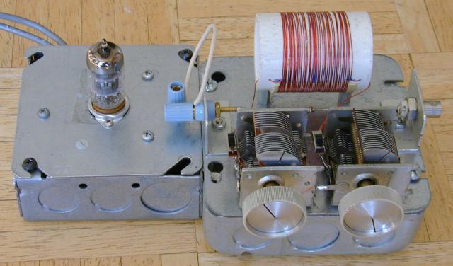
80 meter crystal controlled version of the Little Chickadee transmitter
40 meter VFO/QSK version of the Little Chickadee transmitter, 80 meter osc. coil on left
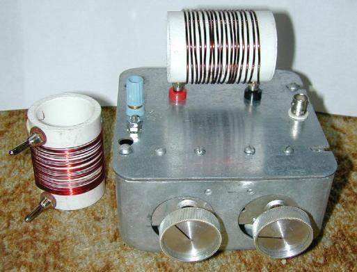
Modular PI output filter V2 with plug-in L2 coils for 80 and 40 meters
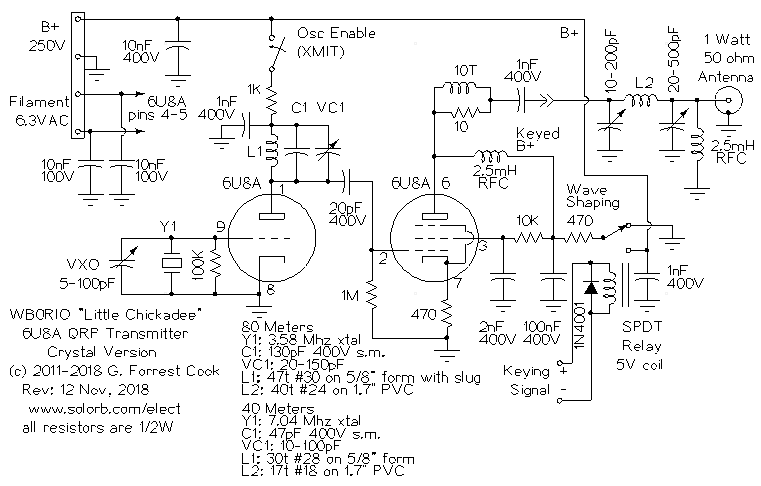
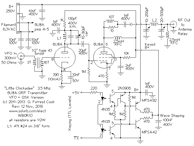
This project involves the construction of a one-tube ham radio QRP (low power) transmitter for the 80 meter or 40 meter band. There are two versions shown, a basic CW transmitter and a CW transmitter with full break-in (QSK) capability. A single 6U8A tube is used for the RF signal path, it contains a triode and a beam pentode in a 9 pin envelope. Output power is around one watt with the VFO version of the circuit, the crystal version may produce less power if the crystal is not very "hot".
One watt is not much RF power but with a good antenna and an open short wave band, the signal can propagate for hundreds of miles. This transmitter features a waveshaping circuit that produces a CW tone that is free of clicks, this makes it sound very good on the air.
The transmitter was originally built as a simple stand-alone crystal-controlled device as shown in the top photo. It covered a small range of frequencies on the 80 meter band by using a variable crystal oscillator (VXO) circuit. The second version of the transmitter added full break-in (QSK) keying and frequency agility via an external VFO. This transmitter is compatible with my Modular CW Transmitter Prototyping System.
Practically speaking, this transmitter is somewhat of an anachronistic design. Similar functionality and much better power efficiency can be achieved with just a few transistors. However, tube projects are fun, educational and they glow nicely. Tube transmitters can survive working into badly mismatched antenna loads that would cause most transistor circuits to self-destruct. Finally, you will likely provide great entertainment for your fellow hams when you tell them you are using a home-brewed vacuum tube transmitter. The Meadowlark direct conversion receiver and the W0RIO Piglet regenerative receiver projects can work in conjunction with this transmitter. The transmitter and receiver can be be powered from the same power supply.
A variation of this transmitter is the AM Chickadee, that device can generate an amplitude modulated signal for transmitting speech and music.
This project involves the use of potentially lethal high voltages including 120 VAC and 250 VDC. The project should only be taken on by someone who has experience working with high voltage circuitry. The power cord should always be removed and the power supply capacitors should be discharged when working on the transmitter.
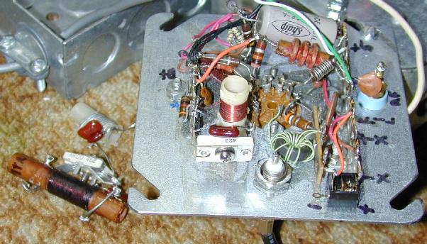
The triode section of the 6U8A is used as a tuned crystal oscillator stage in the crystal version of the circuit and as a tuned amplifier in the VFO version. The triode's tuned circuit consists of L1, a fixed-value silver mica capacitor and a ceramic compressions trimmer capacitor. The photo of the underside of the transmitter shows the triode's 40 meter tuned circuit. An 80 meter tuned circuit and a 15 meter tuned circuit can be seen on the left side of the metal plate.
For 80 meter operation, use the following parts in the triode plate circuit: the silver mica capacitor is 130pf, the trimmer is 20-150pF and L1 is made with 47 turns of #30 insulated wire on a 3/8" cardboard form with a tuning slug. For 40 meter operation, use these parts for the triode plate circuit: the silver mica capacitor is 47pF, the trimmer capacitor is 10-100 pF and L1 is 30 turns of #28 insulated wire on a 5/16" hollow core form. A grid-dip meter may be helpful for adjusting the resonance points of these tuned circuits.
The triode circuit's trimmer capacitor should be adjusted so that the circuit resonates at the crystal frequency. Initial resonance can be set by lightly coupling an oscilloscope probe to the oscillator plate circuit via a 5pF capacitor and tuning for the maximum signal. Final tuning should be performed by tuning the triode circuit while peaking the output power produced by the pentode circuit.
The crystal version of this transmitter is "rock bound" to a particular frequency. Common 3.58 Mhz crystals can be used on 80 meters, but this frequency tends to be occupied by digital-mode signals. It is a good idea to use the crystal oscillator (VXO) variable capacitor to shift the frequency up a few kilohertz to a quiet spot on the band. Other frequencies can be selected by using multiple crystals and a switch or by plugging different crystals into a crystal socket. The oscillator's tank circuit may need to be re-peaked for different crystals if they are more than a few tens of kiloherz apart in frequency.
The output of the oscillator/amplifier triode is lightly coupled to the control grid of the 6U8A pentode through a 20pF DC blocking capacitor. The pentode is biased as a class A RF amplifier, the DC bias current is set by the 470 ohm cathode resistor. The output of the RF amp goes through a VHF parasitic snubber consisting of ten turns of wire around a 10 ohm resistor. Plate voltage is supplied to the pentode through a 2.5mH RF choke coil, this isolates the RF from the power supply.
The output signal from the pentode stage is fed through a low-pass pi filter that matches the tube's output impedance to the 50 ohm antenna impedance. Two plug-in coils were built for L2 in the pi filter, one for 80 meter operation and another for 40 meter operation. See the schematic for the L2 coil details.
In the crystal version of this transmitter, the oscillator's B+ line is switched on at the beginning of transmission with the XMIT switch. Leaving the crystal oscillator on during transmit periods eliminates the chirp that a keyed oscillator may produce. Turning the oscillator off during receive prevents a small amount of "back wave" energy from being picked up in the receiver. In the QSK version of this transmitter, The triode amp's B+ line is driven by the keyed B+ line.
The output amplifier is keyed with the morse code signal by turning the pentode's B+ supply line (plate and screen grid) on and off with a shaped wave that switches between 0V and 250V. In the crystal version of the circuit, an SPDT relay is used for keying the B+ line. The relay should be a small, fast type.
In the QSK version of the circuit, the B+ line is keyed with an isolated solid state keying circuit. The high voltage keying circuit is fairly complex and was designed as an experiment in high-side switching. It would be much simpler to tie the plate circuits to B+ and cathode key both tube sections with a single high voltage NPN transistor.
In the high-side switching circuit the MPSA42 and MPSA92 high voltage transistors are alternately turned on through complementary signals. The 4N35 opto-isolators isolate the high voltages from the TTL level driving waveform and the 2N3906 transistor inverts the opto-isolator's signal to drive the MPSA92. This circuit is essentially a high voltage solid-state relay.
The keying waveform is rounded on the rising and falling edges by the RC filter formed by the 470 ohm resistor(s) and the 100nF capacitor. The shaped keying waveform reduces switching harmonics and prevents the signal from sounding "clicky" on the receive side.
The All-Ears QSK Timing Generator project was used for generating the TTL level keying signal used in the QSK version of this transmitter, the circuit can be added to any keyer with a TTL output. The QSK timing generator provides the inverted TX signal that is used by the transmitter, it also drives the external T/R relay and the receiver mute line.
The power supply is not shown, it should supply anywhere from 175 to 300 Volts DC at 30 mA and 6.3 Volts AC at 1 Amp. The higher B+ voltages will produce slightly more RF power. This power supply is a good match for this transmitter. The power supply that is used in my Howler Monkey amplifier project would also work well for this transmitter, it uses parts that can be purchased new.
The VFO can be any general-purpose device. I use a DDS waveform generator that produces a 300mV P-P sine wave for 80 meter operation. For 40 meter operation, the VFO should produce a bit more output, 500mV P-P should be sufficient. The VFO should have a mute control, my VFO has an opto-isolated mute function that takes a TTL-level drive signal from the QSK timing generator.
The transmitter was constructed on the cover plate of a standard 4"x4" electrical utility box, the plate had a knockout in the center that was perfect for mounting the nine pin tube socket. A larger box is recommended for this project, there is not a lot of extra room in the 4"x4" box. A few extra holes were drilled into the plate for the tube socket screws, the terminal strips and the output connector. A standard romex cable clamp was used to secure the power and keying wires to the box. Keep all wiring as short as possible to lessen the possibility of creating spurious oscillations and other problems.
The antenna tuner / pi filter was built onto a 5"x5" electrical utility box cover plate. In the original version all of the parts were mounted on the top of the plate. The rebuilt version in the third photo has pluggable 80 and 40 meter coils and the variable capacitors were moved to the inside of the box. The two double-section variable capacitors in the pi filter were scrounged from old radios.
Two mini-switch were placed between the sections of the two variable capacitors to give two capacitance ranges, only the smaller section is connected when the switch is off. The switch on the plate side of the tank circuit should generally be left in the off position. The output from the pi filter goes to a BNC jack that connects to the Transmitter input of the external T/R relay.
The RF signal connection between the transmitter and low pass filter boxes was passed through a pair of "banana plug" binding posts and a short wire. Your author originally tried to use a BNC jumper cable here, but the high impedance signal would not pass through the 50 ohm coax cable without severe attenuation. Lesson learned.
For 80 meter operation, the tank coil in the ouput pi filter (L2) has 40 turns of #24 enamel-coated wire hand-wound on a PVC schedule 40 pipe coupler for 1" I.D. pipe. The coupler has an outside diameter of 1-5/8". For 40 meter operation, use 17 turns of #16 wire loosly wound on the same form. The large tank coil is necessary to achieve good "Q", this is important for getting the most output power from the pentode amplifier.
A strip of double-sided tape was used to keep the wire in place while winding the coil. Credit goes to Max Robinson for his excellent article on winding coils. In the second revision of this project, two banana plugs spaced 2" apart were added to the output coil forms. The coil forms plug into two matching banana jacks that are installed in the low pass filter's cover plate.
A well-stocked junk box is the first place to start, your author scrounged most of the parts for this project from discarded electronics. Tubes, sockets and power transformers can be found at Antique Electronic Supply or on eBay. Other parts can be purchased from Mouser, Newark, Jameco or Digi-Key. Any well-stocked hardware store will carry the electrical boxes and plumbing parts that are used in this project.
It is possible to substitute several other types of tube in place of the 6U8A. 6GH8 and 6EA8 tubes have the same pinout as the 6U8A and have both been tried in this circuit with good results. Higher power triode-pentode tubes such as the 6AW8A and 6BM8 could also be used in this circuit with the appropriate pinout changes.
A ham radio license is required to transmit in the ham radio bands. Connect the power supply and keying signals to the transmitter and apply power. Connect the transmitter to an SWR meter and connect the output of the SWR meter to an antenna. A resonant dipole is a good antenna choice. Adjust the pi filter for the best power and SWR readings. The capacitor on the tube side of the pi filter should be adjusted for peak forward power and the capacitor on the antenna side should be adjusted to the point where forward power just starts to drop off.
Once the transmitter has been adjusted, start calling CQ and listen for a response. Operating QRP on 80 and 40 meters requires some strategy since the bands can have very high background noise levels and lots of static from lightning. You will likely have the best results at night time in the winter but contacts can be made year-round. Be sure to appreciate the efforts made by the ham operators who are willing to dig through the noise to contact you with your low power signal.
Back to FC's Ham Radio Circuits page.