(C) 2008 G. Forrest Cook
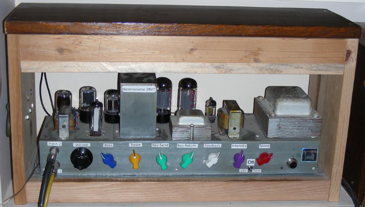
Hammonator 2RVT build 2, Click on above photo for a larger image.
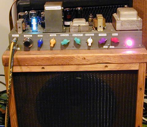
Hammonator 2RVT build 2 on a speaker box before moving it to a wood case.
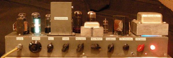
Hammonator 2RVT build 1.
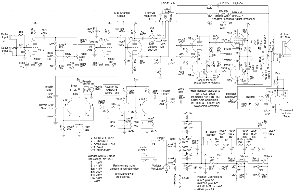
Hammonator 2RVT amp schematic
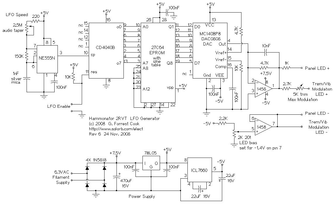
Hammonator 2RVT LFO schematic
This project is a feature-added version of the Hammonator 1 Hammond AO-14 organ to guitar amplifier conversion project. The Hammonator 1 circuit works as a basic guitar amplifier, this version adds some very nice sounding vacuum tube audio effects. The 2RVT model number means: 2nd Generation, Reverb, Vibrato and Tremolo. Two copies of the Hammonator 2RVT amp have been made (see photos), both have been working nicely for many years and the design has stood the test of time.
In year 2022, a few changes were made to this design. The bias circuit was changed to full-wave rectification and individual bias adjustments were added for the two output tubes. An output transformer snubber circuit was added to protect the transformer from the possibility of high-frequency arcing. A grid stopper resistor was added to the vibrato return circuit to reduce the chance of RF pickup. An optional balance resistor was added to the output transformer primary and an optional balance adjustment trimmer was added to the phase inverter stage. The schematic went through a number of improvements, capacitor voltage ratings and resistor wattage ratings were verified and updated where necessary.
The reverb uses a classic-sounding tube circuit with two 6SN7 triode sections in parallel wired as a class A amp driving an 18" Hammond/Accutronics reverb pan. The reverb has both dwell (input) and output level controls. A pitch-shifting vibrato / volume shifting tremolo circuit can be switched into the signal path. The vibrato produces a variety of interesting phase shift sounds, from slow movement to a rapid warbling sound.
Stereo vibrato can be achieved by chaining a second "clean channel" amp's input to the Hammonator's second input jack, or by driving the amp from the "Side Channel Output" connection. Stereo greatly enhances the vibrato effect, the sound appears to move around the room. A cheap guitar practice amp makes an ok secondary amp, a tube amp such as the Spartacus or the Howler Monkey will produce an even better sound. The Tremolo/Vibrato switch alternates between the pitch-shifting vibrato effect and a more conventional volume-shifting tremolo effect. The wide range of LFO speeds can produce many interesting vibrato and tremolo effects.
Compared to the Hammonator 1, some extra wiring was added to the 6AV6 triode tube to support the vibrato/tremolo effects. The audio signal path is still 100% vacuum tubes. A stand-alone sine wave LFO oscillator board was added, it is used for modulating the vibrato/tremolo circuit. The LFO uses relatively modern digital circuitry to produce a high quality LFO waveform across a wider frequencies range than a typical vacuum tube phase-shift oscillator circuit can produce. The LFO circuit is powered by the filament supply, the 6.3VAC is rectified and filtered to produce 7.5VDC.
Another subtle feature of this amp is the use of 100nF capacitors across the electrolytic capacitors on most of the 6SN7 cathode bias circuits. The electrolytic capacitors work well at low frequencies, but have a lot of internal inductance which reduces their effect at higher frequencies. The 100nF caps work well at higher frequencies. Paralleling the two caps produces a "super cap" that gives the amp a smoother frequency response. The 220nF capacitor across the B4+ line completes the loop by improving the frequency response across the 22uF electrolytic capacitor. All of these extra capacitors may be considered optional parts.
The optional 33 ohm resistor in series with the brown primary lead of the output transfomer offsets the extra resistance that is due to this winding being underneath the blue primary winding. This helps to balance the two phases of the push-pull output tubes. The phase inverter balance circuit was added to the plate circuit of VT4a, this allows the output of the two phase inverter triodes to be matched precisely. To set the potentiometer, put a 1Khz sine wave signal into the input and connect a 2 channel oscilloscope to both junctions of 1500 and 220K ohm resistors, set the scope to subtract the two channels and adjust the control for the minimum signal.
The vibrato/tremolo sine wave generator is a fairly involved sub-circuit to build. It may be prudent to start with the Hammonator Model 1 amp and add the vibrato/tremolo circuitry later. Be advised, the vibrato effect is worth the extra effort.
The 6HU6/EM87 indicator tube and associated components can be left out of the circuit or added later. The eye-candy effect is certainly worth a little extra wiring. Other magic eye tubes may be used by making the appropriate wiring changes.
This is a fairly advanced-level project. It takes a lot of technical skills to deconstruct and reconstruct the amplifier circuitry. Also, there are lethal high voltages inside of this amp including 120 VAC, 730 VAC and 420 VDC. The project should only be taken on by someone who has experience working with high voltage circuitry. The power should always be removed when working on the amp, the circuitry is designed to discharge the capacitors when power is removed, but it's always a good idea to short out the electrolytic capacitors before working on the amp.
AC Power Input - grounded 120 VAC, 62 Watts
Guitar Input 1 - High Impedance
Guitar Input 2 - High/Low Impedance
Reverb Send
Reverb Return
Side Channel Output - High Impedance
Speaker Output - 8 ohms, 18 Watts
On/Off (on the back)
Input Volume
Bass
Treble
Reverb Send (Dwell)
Reverb Return
Feedback (Gain)
Vibrato/Tremolo Depth
Vibrato/Tremolo Speed
Vibrato/Tremolo Selector
A friend of mine loaned me his vintage Magnatone Lyric amplifier, the amp has an incredible sounding pitch-shifting vibrato circuit that uses a varistor-based phase modulation scheme. The pitch-shifting vibrato effect could be described as liquidy or warbly and is similar to the sound produced by a rotating Leslie speaker. The type of varistors used in the Magnatone amps are no longer manufactured and they are difficult if not impossible to find. The Magnatone's differential high voltage varistor drive circuitry also takes numerous tube stages to implement.
The vibrato circuit in the Hammonator 2RVT uses a much simpler light dependent resistor (LDR) circuit to produce the required phase shift. The VFO used here has a much wider range of frequencies than the Magnatone's simple Tube VFO, this allows it to produce some amazing slow motion effects.
There is an excellent Geofex article on The technology of phase shifters and flangers that covers the Magnatone circuit and more. Another excellent source of Vibrato circuit information is Magnatone Vibrato Design by Tim Robbins. A good demonstration of pitch-shifting vibrato can be heard in the Lonnie Mack song Wham (YouTube), which features a stereo Magnatone amp. This song is also reportedly where the guitar Whammy Bar got its name.
The phase shifting vibrato circuit used in the Hammonator 2RVT was inspired by the transistorized Univibe circuit from the Geofex article, it is also similar to some Hammond organ vibrato circuits. The Liquidator Tube Phaser/Chorus Effect was an offshoot project that takes tube-based phasing and chorus to the next level, it has three phase-shift stages with individual mixers and a feedback control.
See the Hammonator 1 project for the theory of this amplifier before the reverb, vibrato and tremolo effects were added.
The Vibrato circuit is quite simple. The 6AV6 tube is running as a simple cathodyne phase inverter, similar to the circuit that drives many push-pull amplifier output stages. The signals on the plate and cathode of the tube are 180 degrees out of phase. When the Tremolo/Vibrato switch is set to Vibrato, the Light Variable Resistor (LVR) causes the output signal to shift from one phase of the signal toward the other, depending on the amount of light coming out of the associated LED.
When the Tremolo/Vibrato switch is set to Tremolo, one end of the LVR is connected to ground through the variable intensity resistor. As the light level on the LVR changes, the output signal is raised or lowered.
Power for the LFO board is pulled from the 6.3V filament supply and full-wave rectified and filtered to produce 7.5VDC. The Schottky diode bridge rectifier produces a higher output voltage compared to silicon diodes, this is important for making enough voltage regulator input voltage. The 7.5VDC is regulated by the 78L05 regulator to produce 5VDC. The 5VDC power is inverted with the ICL7660 chip to produce -5VDC. These three DC voltages power the rest of the LFO circuitry.
The 555 timer IC is wired for astable operation to provide a digital clock signal. The speed of the oscillator is controlled by the 2.5M potentiometer. Ideally, the 2.5M speed control pot should be logarithmic taper. Unfortunately this part is very hard to find. If a more common audio-taper (reverse log) potentiometer is used for the speed control, it should be wired so that counter-clockwise is fast and clockwise is slow. This allows the LFO speed adjustment to have a normal feel.
The LFO circuit is basically a stepped digital sine wave generator. The variable square wave clock signal from the 555 timer drives a CMOS 4040 binary counter IC. The lowest 8 bits of the 4040 counter are used to generate addresses in the range of 0 to 255. The addresses are fed into the 27C64 EPROM. The EPROM is programmed with 256 steps of a digitized sine wave. The Digitized sine wave values are fed to the DAC0808 DAC, which converts them into analog currents for driving the 1458 output op-amp. The second half of the 1458 dual op-amp biases the negative side of the LEDs below zero volts so that the LEDs are just turning on at the low point of the LFO waveform.
Here are some Intel hex format files for programming the EPROM: Regular Sine Wave and Exponentially Weighted Sine Wave. The latter wave is recommended since it compensates for the LED/LVR non-linearity.
The op-amp on the output of the DAC converts the DAC output current into voltages in the range of 0-10V. The 100nF capacitor in the op-amp's feedback loop smooths out the steps in the sine wave. The LED/LVR optocoupler is driven by this sine wave voltage. The LED current is limited by the 2.7K resistor and the maximum phase deviation is adjusted with the 5K trimmer. The phaser effect's intensity is adjusted by varying the 100K pot that is in series with the light variable resistor (LVR).
A microprocessor-based LFO circuit such as my Arduino LFO V1 or my Arduino LFO V2 will also work in this amplifier. Those designs use fewer parts and don't require an EPROM programmer.
The negative side of the LED/LVR and the front panel LED are connected to an adjustable DC bias circuit which is set to around -1.4VDC. The bias is set so that at the zero point on the sine wave, the LED is just beginning to emit light. At the 10V point on the sine wave, the LED reaches the full brightness as determined by the intensity control. The LED bias insures that the response of the LVR is fairly sinusoidal, if the LED were not biased, the bottom of the sine wave would be effectively cut off.
The Tremolo/Vibrato switch is a DPDT 3 position center off type. When the switch is in the middle (off) position, the LFO enable line is pulled high by the 10K resistor, causing the 4040 counter to reset, this causes the DAC to stop generating waves and turn off the LEDs.
In addition to the new vibrato circuitry, a number of changes were performed on the Hammonator 1 to create the Hammonator 2. Additional front panel holes were drilled for the extra input and the vibrato knobs and switch. The vibrato front-panel LED was mounted in an existing screw hole. The tubes were re-numbered, the 6HU6/EM87 was changed from VT7 to VT8 and the new 6AV6 was numbered VT7. In one of the photos above, a blue glow can be seen under the power transformer, this effect was created by hot-glueing a piece of blue plexiglass between the pilot light and the chassis.
The black cardboard-coated electrolytic capacitor was removed because it vibrated and buzzed when exposed to loud sounds from the speaker. Old electrolytics tend to emit funky chemical smells when they get hot and their capacitance drops, causing hum. Old electrolytic capacitors can also short out, this can destroy the power transformer. It is a good idea to alway replace all electrolytic capacitors with new parts when re-building old tube amplifiers.
The signal lines to the 6AV6 cross over the power amp circuitry, it is critical to run these through shielded (coaxial) cables to avoid parasitic feedback issues. Only ground the input side of the shielded cables to prevent a ground loop. A 3.3K/5nF RC array was added to the power amp's feedback loop and the pad resistor on the feedback control was increased to 750 ohms, these changes took care of an RF oscillation issue.
The high voltage filter circuit was modified from the Hammonator 1 circuit to include a standby switch for turning the B+ supply on and off. Tube life can be improved if the tube filaments and cathodes are warmed up before applying B+ voltage to the tubes. My Vacuum Tube B+ Delay circuit was installed in both versions of the Hammonator 2 RVT amp, it replaces the standby switch and provides automatic power sequencing.
The bias circuitry for the output tubes was duplicated so that each tube gets its own bias adjustment pot. The bias rectifier circuit was also converted from half-wave to full-wave with the addition of another 1N4007 diode. This change reduces the level of hum that is injected into the output tube control grids. The bias adjustment circuit was inspired by an article from from The Valve Wizard. This helps the amp to work better with tubes that are somewhat mis-matched, which can help when using vintage tubes.
The 6SN7 reverb driver tube V2 in the Hammonator 1 ran fairly hot due to the high bias current set by the 560 ohm cathode current and B5+ voltage. A 6SN7GTB (or 6SN7GTA) tube, which both have higher plate dissipation ratings compared to a regular 6SN7, should be used in this position.
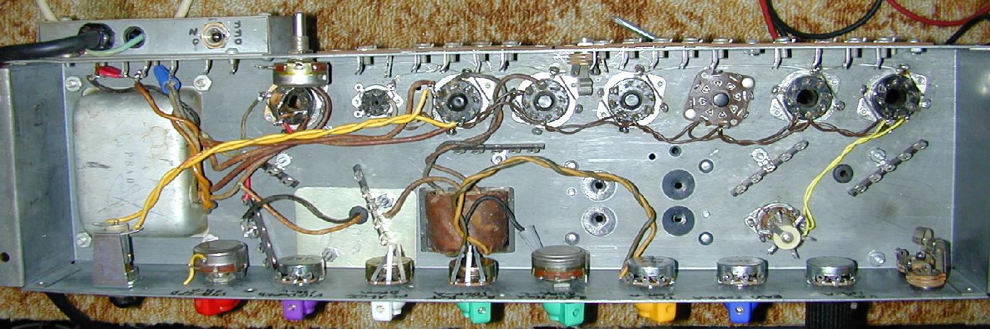
The Hammonator 1 article explains most of the amplifier conversion process. This photo shows the stripped inside and terminal strip locations of the Hammonator 2 RVT and this second photo shows the completed inside wiring, the LFO board can be seen on the left side of the chassis.
The vibrato circuit's optical coupler is constructed by placing a LVR and a medium brightness red LED inside of a piece of heat shrink tubing. The wires from the LED and LVR should be covered with pieces of wire insulation to prevent shorts.
The LFO circuit board was built on a 0.1" grid perforated board. Connections were hand-soldered to solder type IC sockets. Soldered wire-wrap wire was used for most of the wiring, some #22 solid wire was used for the ground connections. The board was built to fit on the side of the chassis next to the power transformer, it was a very tight fit. A piece of clear plastic from a soap bottle was cut to the same outline as the board and installed between the board and the chassis to prevent shorts. The wiring from the LFO board to the front panel potentiometers should be done with shielded wire to prevent pickup of the oscillator signal by the amp's input circuitry.
This amplifier drives a 15" guitar speaker nicely, this gives a baratone tone quality. A more conventional 12" guitar speaker is also a good match for the amp and produces a brigher sound. The 15" speaker was mounted in a heavy duty wood box that was made from 2x10 dimensional lumber (top, bottom) and 2x8 (sides) with a 3/4" plywood front and two 3/8" plywood back plates with a rear air gap.
When building guitar speaker cabinets, it is a good idea to feed an amplified sine wave signal through the speaker and vary the frequency to ferret out any cabinet buzzing points. If the cabinet buzzes at a certain frequency, you can poke and flex the cabinet corners and speaker mounting points to locate the source of the buzz. A little wood glue can stop many buzz points, be sure to use nuts and bolts on all of the speaker mounting holes. In some cases, it can be helpful to add wooden ribs or braces to the inside of the speaker box.
The amplifiers were originally built on top of speaker cabinets and the reverb tanks were placed inside the bottom of the speaker cabinets to enhance the sonic coupling between the speaker and reverb springs. This setup was deemed too fragile and it was also too heavy, so the amps were moved to stand-alone wooden boxes. The reverb assemblies were mounted above the amp on a small shelf that is part of the boxes. The reverb pickup coil should be placed on the opposite side from the amp's power transformer to prevent hum pickup.
The basic volume and tone controls on the Hammonator 2RVT amp are operated in the same way as the Hammonator 1. The Tremolo/Vibrato switch selects the tremolo or vibrato effect, or neither when it is in the center-off position. The Intensity control selects the depth of the vibrato or tremolo and the Speed control varies the rate of the effect. Unlike classic 1960s amps, the vibrato/tremolo VFO speed control covers a much wider range of frequencies and produces a more accurate sine wave response across those frequencies.
The reverb send and return controls should be adjusted for the best sound. It is a good idea to turn the reverb return control to maximum before setting the reverb send control. Once you achieve the desired reverb sound, reduce the reverb return control to get the appropriate mix.
To get the full stereo vibrato sound, be sure to run a second amplifier in parallel with the Hammonator 2RVT. The second amp's input can be plugged into either the Guitar Input 2 jack or the side channel output jack.
Back to FC's Music Circuits page.