
(C) 2010-2022, G. Forrest Cook
The Squirrel Monkey combo amp.

The Squirrel Monkey combo rear view with 6 inch speaker.
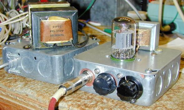
The Squirrel Monkey amp and power supply boxes.
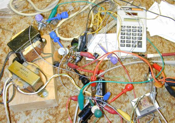
The Squirrel Monkey being prototyped, this mess actually worked.
After building the full-featured Hammonator 2RVT and Lil' Tiger amps followed by the simpler Spartacus amp, your author decided to go in a completely different direction and design a minimalistic class-A guitar practice amp. Enter the Squirrel Monkey. The Squirrel Monkey amp is unusual in that it uses a three-element 6AF11 Compactron tube which packs a high gain triode, a medium gain triode and a beam-power pentode into a single glass envelope.
The amp was originally going to be called "the Chimp" in reference to the Fender Champ, but that name has been used by others for different amps, so this amp was named "the Squirrel Monkey" after the diminutive primate. The Squirrel Monkey amp has a triode-triode-pentode layout that is similar to the original Champ and can be thought of as a "Champ in a bottle". However there are a number of differences from the Champ design, especially around the power supply and tone control circuitry.
The Squirrel Monkey is a simple design with only two controls, volume and tone (high-cut). The amp produces around 0.8W of audio power, that is loud enough to work as a practice amp or a recording amp. The tone is very clear at low volume and the hiss level is low. If the amp is turned up, it turns into a power fuzz-box, producing lots of distortion that is typical for a cranked single-ended class-A amp. The 120VAC input power consumption was measured at 13 Watts while idle.
The Squirrel Monkey was constructed in two sections, the power supply and the amplifier circuitry. Each of the sections was built onto a pair of common 4"x4" electrical utility boxes. It is also possible to build the Squirrel Monkey into a more typical guitar amp chassis, be sure to locate the 6AF11 tube and input circuitry away from the power transformer to prevent hum.
This project uses high voltages including 120VAC and 200VDC. The project should only be taken on by someone who has experience working with high voltage circuitry. The power cord should always be removed when working on the amp, the circuitry is designed to discharge the capacitors when power is removed, but it's always a good idea to briefly short out the electrolytic capacitors before working on the amp.
Power Input - grounded 120VAC
Guitar Input - High Impedance (1M)
Speaker Output - 8 ohms, 0.8W
On/Off
Volume
Tone
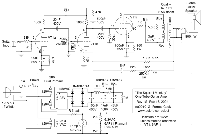
The guitar input jack feeds into class-A preamp VT1a through a 33K grid stopper resistor, which eliminates sensitivity to radio frequency interference. VT1a is the single high gain triode section in the 6AF11. The preamp output feeds into the volume control pot, and that drives the power amp circuitry, VT1b and VT1c. The 3.3M resistor on the grid of VT1b helps to remove scratchy sounds that may come when the volume control pot is turned.
VT1b is the first gain stage in the power amp, it includes negative feedback input on the cathode and a high cut R-C network on the plate which reduces sensitivity to ultrasonic sounds. VT1b feeds the output stage, pentode VT1c through a 20nF capacitor. Both VT1b and VT1c are running in class-A mode. The pentode of VT1c is cathode-biased to the tube's optimal 24mA by the 160 ohm resistor. The 180K resistor from the transformer output to the VT1b cathode adds a small amount of negative feedback for stabilizing the amplifier. The 3nF capacitor and 5.6K ohm resistor across the output transformer primary winding keeps the output stage from oscillating at radio frequencies.
The tone control is somewhat non-standard, it involves an adjustable high-pass network around the power amp's negative feedback loop. The negative feedback inverts the high-pass function into an adjustable high cut filter. This form of tone control has the advantage of not reducing the gain of the preamp stage like many guitar amp tone stacks, those can be quite lossy.
There are a lot of Fender 5E3 fans out there who think that negative feedback is a bad thing in any form. From my experiments, I have found that the secret of negative feedback is to use just a minimal amount. The NFB greatly reduces the production of bad-sounding distortion, while preserving the good-sounding vacuum tube distortion and punchy presence. Bad-sounding distortion is visible on an oscilloscope as squared waves, pointy spikes, asymetric waveforms and even radio frequency oscillations. Good-sounding distortion is visible as the soft rounding of the tops of the waves as a result of plate starvation.
A number of different junk-box output transformers were tried in this circuit with minor variations in performance. A 3.5K to 8 ohm transformer produced the most power output of the transformers that were tested. Since this is a relatively low power amplifier, it is not nececessary for the output transformer to be perfectly matched to the tube, although the volume will be loudest when the match is correct. Transformers with input impedances from 2.5K to 10K should work and a common 5K to 8 ohm transformer would be a good choice if you cannot locate a 3.5K to 8 ohm unit.
The power supply section uses a standard 6.3VAC/2 Amp filament transformer for powering the tube filaments, the two 220 ohm resistors to ground help to cancel out filament-induced hum. If you use a filament transformer with a center-tapped output winding, ground the center tap and eliminate the 220 ohm resistors. If the filament transformer's output voltage is much higher than 6.3V while driving the 6AF11 and pilot light, it is a good idea to trim the voltage to true 6.3VAC with a small series dropping resistor. This resistor is labeled R-fil-adj in the schematic and it will help to extend the life of the 6AF11 tube. A value between 1/2 ohm and several ohms at 1 watt should be about right.
The high voltage transformer uses a bit of trickery that has been seen on other small amplifier designs. A 28VAC/1 Amp (1/2 Amp would work) transformer with dual primaries is wired so that one primary winding is used as a secondary winding and the 28V secondary voltage is connected in series and in phase with that 120V winding to produce 148VAC. This is fed into a bridge rectifier to produce the high voltage DC, which is around 210V with no load. A more common 24VAC output dual-primary transformer will also work here.
The high voltage DC is filtered through a choke input RC filter to remove hum and produce a steady B1+ supply. The 1H choke is not required, but it helps to reduce hum, a 500mH choke could be substituted. The choke can also be replaced with a 50 to 100 ohm, 2W resistor. The B1+ supply runs at around 180VDC with the tube plugged in. The B1+ supply is further filtered through another R/C filter to produce an isolated B2+ supply for the first two gain stages, this runs at around 175V. The 2M resistor is used to discharge the electrolytic capacitors when power is removed.
The project was built almost entirely with junk-box parts that were scrounged from old radios and TVs. Most of the parts for this amplifier project can be purchased from mail order electronic suppliers such as Mouser, Digi-Key and Jameco. The 6AF11 tube and 12 pin duodecar Compactron socket can be found on eBay for reasonable prices.
The output transformer, power supply choke coil and high voltage capacitors are available from Amplified Parts or other amplifier parts sources. Jameco.com part 101864/XFR2424Q should be suitable for the power transformer. Amplified Parts sells the Hammond P-T154M 2H, 200mA choke and Hammond P-T1750F output transformer, which should both work for this project. Mouser.com is a good place to find diodes, resistors, jacks and potentiometers. See The Strat Monger for many other parts suppliers.
The amplifier and power supply sections were built onto cover plates of standard 4"x4" electrical utility boxes. A chassis punch was used to cut out the 1-3/16" hold for the 6AF11 compactron socket. It would be a good idea to add more physical protection around the vacuum tube such as U-shaped rack handles. Numerous other holes were drilled to mount the transformers and a few terminal strips. Most of the amp wiring was done between the tube socket and the terminal strips in a fairly high-density manner.
Three chassis knock-outs were removed on the front and back of the amp's utility box chassis. Pieces of double-sided circuit board were cut to fit into these spaces and holes were drilled into the circuit board pieces for the jacks and controls. Aluminum plates could also be used. Standard Romex-style cable clamps were used on the power supply box for securing the power input and output wires.
The two metal boxes were installed in an open-backed speaker cabinet with a 6" speaker. The power supply box was mounted on the bottom of the cabinet and the amplifier box was mounted under the top.
Beginners would be advised to use larger enclosure for the electronics. An old 5-tube AM radio would make a spiffy box for this project. The speaker would probably need to be upgraded. An 8 ohm car stereo speaker would be a good choice since they are small and can handle more power than a radio speaker.
Plug in the AC power cord. Plug an electric guitar into the input jack. Tweak the knobs for a good sound. Play the guitar and enjoy the warm tube sound. This is a fairly high-gain amplifier and it can overdrive quite easily. If you want a clean sound, be sure to keep the volume control low. Turn up the volume control for more fuzzy distortion. If you like the Squirrel Monkey amp check out its successor, the Howler Monkey, a very different animal indeed.
This amplifier also works well as a nearly indestructible piece of test equipment. It can be used to trace signals through amplifiers or other audio equipment. If you intend to use the amp this way, add a 50nF (0.05uF) capacitor in series with the input to prevent any external bias voltages from reaching the grid of VT1a. Another use for the amp is as an audio stage for experimental radios such as the Piglet regenerative short wave receiver.

Back to FC's Music Circuits page.